


Cast Welded Joints of the Chicago City Railway Company in 1899
Cast welded joints were made with a variety of different molds for the Street Railways of Chicago under a license from the Falk Company, as shown in the following publication:
Roadbed Construction in Chicago
Street Railway Journal, Vol 15, No 10, October, 1899, p. 636-642.[1]
The building of electric railway track in Chicago has been along simple lines and with but little variation of practice. No concrete is used as substructure, but 7-in. and 9-in. (178 mm x 229 mm) girder rails are spiked directly to ties laid on dirt or on a light layer of broken stone or gravel at the bottom of an excavated trench. The standard construction of the Chicago City Railway is shown in the accompanying photographs and sections.
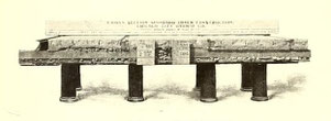
Fig. 23. — End view
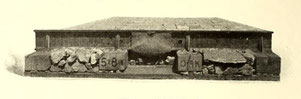
Fig. 24. — Side view (showing 5 x 8 in (127 x 200 mm) oak sleepers)
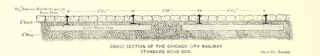
Fig. 25. — Chicago City Railway roadbed
This construction, on 6 ins. (152 mm) of broken stone, is used by the company for 10 miles (16 km) of track- on Halstead Street. In the subconstruction recommended by the engineers of the Chicago
Union Traction Company, which has, however, been used only on the Lake Street extension, oak ties 5 ins. x 7 ins. x 6½ ft. or 7 ft. long (127 mm x 178 mm x 1981 mm or 2134 mm) are laid 2 ft. (610
mm) apart from center to center, and ballasted to a depth of 8 ins. (200 mm) under the ties, the ballast being thoroughly rolled and strained to level and filled in between the ties. Speaking
generally, it would seem as if enough attention had not been paid in the past in Chicago to a deep and durable substructure, for the soil of Chicago is moist even to muddiness, and the track
frequently shows evidence at the joints of insufficient strength of support.
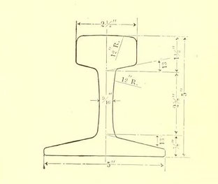
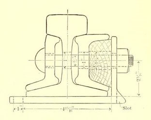
Many rail sections have been used in times past, but practice is generally settling down to the section shown in Fig. 28, which is the Lorain Steel Company's 7-in. 85-lb. section (178 mm, 42,5
kg/m). The same company's 9-in. 93-lb. section (229 mm, 46.5 kg/m) is also used in places as well as the 9-in. 90-lb. Cambria sections (229 mm, 45 kg/m) shown in Figs. 26 and 27. The elevated
lines use an 80-lb. (40 kg/m) 5-in. (127 mm) T. rail of A. S. C. E. standard section (Fig. 46).
All new purchases of rails by the Chicago surface companies specify 60-ft. (18,29 m) lengths.
The Falk cast welded rail joint is the standard three large Chicago surface systems, and all have now taken out a license from the Falk Company to do their own welding. How carefully the details
of the cast weld joints are worked out, both for old and new track, may be inferred from the number of the Falk joint molds used by the Chicago City Railway Company, as shown in the accompanying
engravings.
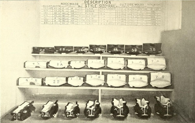
Fig. 31. — Cast weld joint molds — miscellaneous sections
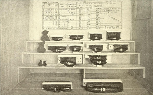
Fig. 32. — Cast weld Joint molds — miscellaneous sections
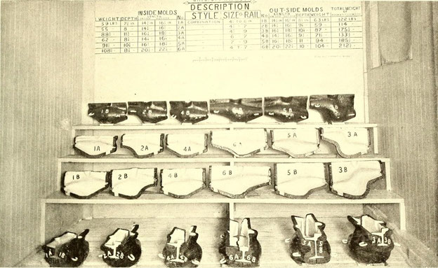
Fig. 33. — Cast weld combination with joint wolds
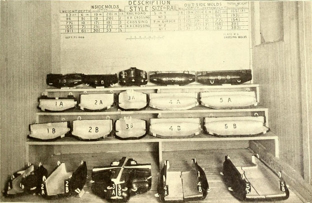
Fig. 34. — Cast weld railroad crossing joint molds
The Chicago City Railway Company was one of the first in the country to adopt this joint, about 40,000 joints being welded in 1895 and 1896, while there are now nearly 100,000 joints on its system. Complete welding outfits with licenses are now owned by the North Chicago Street Railroad Company, the West Chicago Street Railroad Company, the Chicago Consolidated Traction Company and the Chicago City Railway Company, and the Calumet Company reports that it is intending to cast weld its future work by either the Falk or the “American Improved” process.
The Northwestern and Union Loop Elevated Railway Companies are using the Weber Joint, following in this respect the practice of the Manhattan Company in New York. The Chicago Weber joint s illustrated in Fig. 47. It is 24 ins. (610 mm) long (920 mm) with four ¾-ins (19 mm) bolts and nuts fitting A. S. C. E. section of the 80-lb. (40 kg/m) rail. About 48 miles (77 km) in all have so far been fitted with the Weber joints.
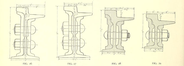
Fig. 26-29.
— Rail sections and joints used in Chicago
As may naturally be supposed, there is an immense amount of complicated and most expensive track "special work" in Chicago. In addition to the great number of crossings, loops, curves, etc., of
the street railway lines proper, there are far more crossings with steam railroad lines than are ordinarily found in a city, Chicago being a great railroad center with tracks coming into the
business heart of the city at grade in almost all cases. In addition to this, there are further complications from the crossing of cable lines with each other and with electric and horse
railways, so that altogether Chicago is an excellent place to study how to solve complicated engineering problems in track construction.
For example, the Weir Frog Company not long ago made for the West Chicago Street Railroad Company two most complicated nests of crossings at Clinton and Randolph Streets and Clinton and Madison
Streets. These crossings are of unusual length, the intersections between switches measuring 130 ft. (39,6 m), and between centers of opposite curves about 57 ft. (17.4 m). Composing each set of
crossings there were sixteen frogs, four special, open hearth, caststeel, double switches and mates, four single switches and mates, four 90-deg. angle crossings and six 38-deg. angle crossings.
All were made from 9-in. Cambria guard rail of weight 104 lbs. and 107 lbs. per yard.
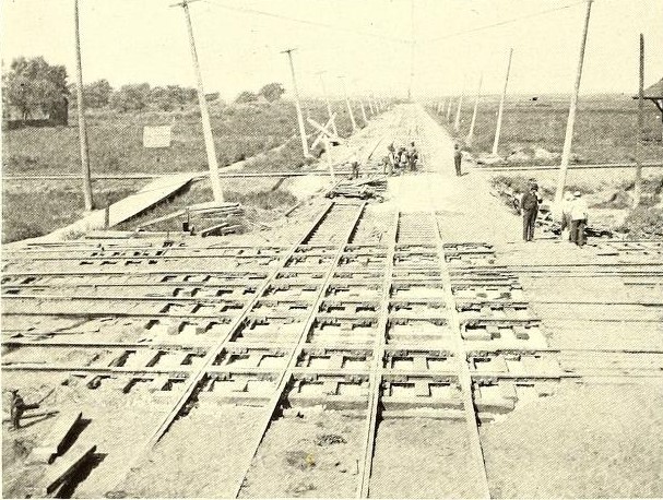
Fig. 35. — A Chicago Surface and steam railroad crossing
The Johnson "built up," "cast-steel" and "guarantee" work is also used extensively in Chicago, while the Chicago City Railway Company uses the hardened center frogs, mates, switches, etc., of the
Pennsylvania Steel Company in building its own crossings and other important special work.
In Fig. 36 is shown a cable curve and trolley crossing recently put in by the Chicago City Railway Company at Twenty-second Street, Indiana Avenue and Cottage Grove Avenue, and it may be
interesting to speak of the way in which the old, worn-out crossing was taken out and the new one put in, as illustrating the rapidity with which such work can be done.
The new construction of the inside curve was put in position on the night of July 18, (1899) and that of the outside on the night of the 26th of July (1899). The paving and concrete had
previously been removed, the track and slot rails cut, bolts loosened and everything made ready. The old construction of one track was removed and the new section, together with the cable
pulleys, was put in ready for the operation of the cars, after the cable stopped running at 1 o'clock, and the line was ready for service at 5 o'clock in the morning — this without even
interrupting the running of the night horse cars. About fifty men with three overseers were required to do the work, the scene being lighted up by the ordinary torches employed for night work,
and by special electric lights suspended on poles from the trolley wire, and lighted from the trolley circuit. Each curve with its portion of the crossings had previously been set up complete, in
the rail yard of the company, and each man had been given instructions as to how he should perform his part of the labor when the section was to be put in place, so that by this drill the
installation was effected in an incredibly short time, as noted above.
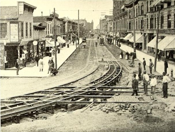
Fig. 36. — Chicago Cable crossing
This curve is of about 80-ft. (24,3 m) radius, and extends about 50 ft. (15,2 m) on Twenty-second Street, and about the same distance on Cottage Grove Avenue. In the new construction cast yokes
were employed in place of the wrought iron yokes of the old construction. A 7-in. (178 mm) rail was employed, with 7¾-in. (197 mm) guard rails. This curve was constructed by the Falk
Manufacturing Company, of Milwaukee, and was installed by Assistant Superintendent Heidelberg and Track Master Stephens, of the Chicago City Company.
The practice is becoming quite general in Chicago of omitting copper bonds where cast welded joints are made, it being held that the close union of metals brought about by pouring the molten iron
around the rail sections in the process of cast welding, forms an electrical connection of greater conductivity than the rail itself, which is, of course, all that can be desired. In order to
promote this union great care is taken by all the companies when weld- ing the rails to clean the ends thoroughly by a sand blast. Cross bonds are, however, used every 500 ft. (152 m) in order to
unite in parallel the conductivity of the two rails. With ordinary fish-plate joints, however, of which there are still a great many in Chicago, the usual copper bonds, of practically all
existing types, are employed.
See also
Rail Welding: Gapless rail track for railways, tramways, subways and cranes
• Cast Welding 1894: Falk Mfg. Co. laid 3 mi of continuous track at St Louis
— Cast Welding 1896: Falk
Mfg. Co. produced
60,000 cast welded joints
— Cast Welding 1905:
Experiences with a historic welding process
References
- Roadbed Construction in Chicago. Street Railway Journal, Vol 15, No 10, October, 1899, p. 636-642.