


Electric Welding: Continuous Rail Experiment at the Baden & St. Louis Railroad
The following article gives an insight into the application of an electric welding machine made by the Thomson Electric Welding Company in 1894:
Electric Track Welding at St. Louis
Three and One-Half Miles of Continuous Rail.
The Baden & St. Louis Railroad the Second to try the Continuous Rail Experiment.
The First New Track so Laid.
By Richard Mc Culloch,
Electrical Engineer, Cass Avenue & Fair Grounds Electric Railway, St. Louis.
The Street Railway Review, 1894, p. 263-266.[1][2]
To build a track which would obviate the ceaseless trouble with joints and to perpetually insure a smooth and easy riding roadbed, was the object of the management of the Baden & St. Louis Railroad when, last February (i.e. in February 1893), it closed a contract with the Johnson Company to weld together the rail ends of its reconstructed road.

The Welding Car (Johnson Company N° 10, Electrical Department)
In the past few years there have been several experiments with continuous track, and all tend to show that the difficulties which would be supposed to arise from contraction and expansion can be
neglected. The most scientific and thorough experiment along this line was made by A. J. Moxham, president of the Johnson Company, early in 1892, and reported to the American Street Railway
Association, at Cleveland, in that year. In this case the rails were so bolted together as to be practically continuous.
Previous to this Philip Noonan laid some track with hot riveted rail joints, on the Lynchburg & Durham Railroad, near Gladys, Va. Some time ago C. W. Wason, of the Cleveland Electric Railway,
laid some track with hot riveted rail joints.
All of these trials gave satisfactory results. Last year (i.e. 1893), the Johnson Company, having procured a suitable electric welder from the Thomson Electric Welding Company, several miles of
track were welded on the West End road, of Boston.
There was some trouble from rails breaking near the welds, but the Johnson Company persevered with its experiments and entered the field this year prepared to guarantee its work. Street railways
have shown a great willingness to try welded track and this season will be one of great activity along this line. The road under consideration is the first to begin welding operations this
season.
The Baden & St. Louis Railroad is one of the oldest street railways in St. Louis, its charter having been granted in 1870. It runs between the north end of the Broadway Cable and Baden, a
suburb in the northern part of the city, passing on its route O'Fallen Park and the two principal cemeteries of the city. The road was formerly operated as an independent horse road, having a
single track with turn-outs, but as it has recently passed under the same management as the Broadway Cable, it was decided to operate the road by electric power and use it as an extension of the
cable road. The road is about three and a half miles long, and is to be double track the entire distance. There are no crossings with other roads, and although there are no sharp curves, it has a
number of long bends of eight hundred to two thousand feet
(244-304 m)
radius. In making the sharper bends, the rails are curved in a rail bender and then welded in place. The street in which the track is laid is an old macadam road, varying in width
from sixty to eighty feet (18-24 m), and is used very much by farmers in bringing their produce to the city.
The current for the operation of the road and for the welding process is obtained from the new Cass Avenue & Fair Grounds Railway power house, this road being under the same management as the
Broadway Cable. The poles for the span and feed wires were all erected before the laying of the track began. The terminus of the Baden road is about two and one half miles from the power house.
Five Number oooo wires are run from the station, four of them being overhead and one a track feeder. As there is no direct rail return to the power house, an additional track connection is
secured in the following manner: The terminal sheave of the cable is well bonded to the first rail of the new electric road, and at a point where the cable track crosses an electric track, the
carrying pulleys of the cable are bonded to the rails of an electric road which runs directly to the power house. In this manner, the cable and conduit act as return conductors.
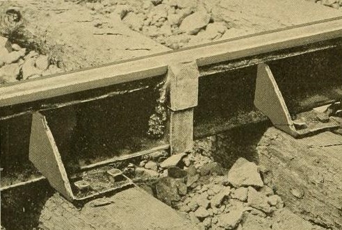
Welded joint, showing lugs
Preparatory to the welding operation, it was found necessary to lay the track, tamp it, line it, and surface it completely before the joints were welded. At the start an attempt was made to weld
the joints first and tamp and surface the- track afterwards, but the weight of the welding car was such that the rail was bent down in the middle and raised at the ends, making joints welded in
this manner high.
The road-bed is first plowed out to the necessary depth. Then six inches of macadam are thrown in and rolled. Upon the rolled surface are placed the hewn white oak ties, three feet apart. The
rails are then spiked to the ties and the track tamped to grade and filled in to the tops of the ties. The rails are then ready for the welding of the joints.

The welding car is equipped with two W. P. 50 motors, with the rheostat, reversing switch, etc., of an ordinary street car. In addition to this it has the welding circuit shown in Fig. 1.
The current from the trolley passes through an automatic circuit breaker, switch, ammeter and starting rheostat to a transformer which transforms from the 500 volt continuous to an alternating current. This transformer resembles an ordinary four pole General Electric 100 kilowatt dynamo. To obtain the alternating current four leads from the windings are taken off at equal distances around the armature and led to two collector rings on the armature shaft. The speed of the transformer is about 1,100 revolutions per minute, so that the periodicity of the alternating current is about 4,400 per minute. The alternating current from the collector rings passes through a regulating induction coil with a moveable iron core to the welding machine, an illustration of which is here given.
This machine is hung on a crane so that it may be set over either rail, and is simply an alternating current transformer on a huge scale in which the rail joint completes the secondary circuit. It was made by the Thomson Electric Welding Company, and operates on the same principle as its well-known machines. The insulation of the coils is paraffine oil and the secondary consists of a single turn of an enormous bundle of sheet copper strips. These strips lead to two copper contact plates, between which the welding is done. The distance between the plates is controlled by a toggle joint operated by a screw, so arranged that by a slight turn of the screw a great pressure may be brought to bear upon the weld.

Welding machine at work
In addition to this circuit, the welding car contains a motor for operating the crane, and another for driving a pump which circulates water in the welding machine.
The car is very heavy, weighing about 30 tons when equipped for work. There is also a small car which carries two motors, operating emery wheels attached to flexible shafts for polishing the
joints preparatory to welding.

The welded connection between the rails is made by means of lugs welded to the web of the rail. A section at the joint is shown in Fig. 2.
It is intended that enough plastic steel shall enter the joint to make a butt weld, and that additional security be afforded by the lugs welded to the web. The bottom lugs, numbers 1 and 2, are
first welded. After they are in position, the operation is completed by welding numbers 3 and 4. It requires from one to two minutes to make each weld. The potential at the welder is transformed
down to four volts. The direct current transformer takes from the line about 250 amperes at 500 volts.
The operation of welding is as follows: The ends of the rails are butted together by driving a wedge in the joint ahead. The welding car is then run over the joint to be welded, and the welding
takes place at the rear of the car, so that it is never necessary to run over a hot joint. The webs of the rails are polished with emery wheels for about two inches on each side of the joint. The
joint is then clamped by means of a gun metal casting, which holds the rails in proper position while the weld is being made. The bottom lugs (Numbers 1 and 2 in Figure 2) are then placed in
position and the contact clamps screwed down upon them.
When the circuit of the secondary coil is thus completed, the switch on the welder is closed and the iron core of the induction coil slowly raised. Almost instantly a dark, ruddy color appears in
the lugs which gradually brightens until the welding heat is reached. A quick turn of the screw which operates the toggle joints brings the lugs firmly up against the rail and forces the plastic
steel into the joint between the ends of the rails. The upper lugs (Numbers 3 and 4) are quickly inserted, the contacts raised and screwed down upon them and they are welded in the same manner as
the lower lugs. Pieces of carbon are previously placed upon the top of the rail so that this portion is carbonized and hardened by the process. After the lugs are welded the tread and flange are
smoothed up by hammering. The welding has been so perfect in many instances, that after the track has been filled in, it is impossible to see the joint in the tread.

The completed track
The greater portion of the time is consumed in preparing the joints, moving the machine, setting up the welder, etc. The machine has been completing 30 to 50 joints per day of ten hours.
At the present writing (1894) no great trouble has been experienced from expansion and contraction. The temperature of the air has varied exceedingly. Several of the joints broke soon after
welding, but these were probably imperfect welds. These joints were re-welded as soon as the break was discovered. No buckling has thus far been noticeable on the warmest days. The track is
filled in as soon as possible after welding, but on several occasions, 300 to 500 feet of welded track have been left open for several days without bad results.
The results have been very satisfactory and the management of the company is very sanguine as to the outcome of the experiment. G. Milton Brown, of the Johnson Company, is in charge of the
operations.
See also
References
- Richard McCulloch: Electric Track Welding at St. Louis. The Street Railway Review. Windsor & Kenfield Publishers, Chicago, 1894, p. 263-266.
- The Electric Welding of Rail Joints. Scientific American, 11 August 1894, p. 91.