


Early Applications of Aluminothermic Welding in America before June 1905
Aluminothermic reactions generate heat by converting Fe2 O3 + 2Al to Al2 O3 + 2 Fe. This heat can be used for Thermit Welding and similar processes.
Thermit powder was invented and initially only made in Germany, but after it could be produced in the United States with effect from June 1904, the benefits of the Thermit process were quickly recognised and it was quickly applied to locomotive repairs, track laying and shipbuilding as well as to the production and casting of steel and iron. A paper by Ernest Stütz describes the early applications as shown below:
The Thermit Process in American Practice
By Ernest Stütz
Read at the June, 1905, meeting of the American Society for Testing Materials[1]
The Thermit Process
Just a year ago (i.e. in June 1904) the first Thermit was manufactured in this country (i.e. the U.S.A.) and the applications developed in Europe by Dr. Hans Goldschmidt, at the works of Th. Goldschmidt, Essen-Ruhr (founded 1847), were transplanted to American soil and have since blossomed forth under the fostering care of American ingenuity.

Analysis of Thermit Steel: Illinois Steel Company, the Rookery, Chicago, Illinois and Pennsylvania Railroad, Altoona

The first is one of pure Thermit steel; the other of the steel in the riser of a welded-steel locomotive frame, drawn out under the hammer into a bar some three feet long and turned down and broken.
The simplicity of outfit and manipulation and the speed with which the reaction does its work are its chief recommendations for industrial purposes.
In a crucible some 20 inches (500 mm) high and therefore easily transportable, in half a minute can be produced 30 pounds (15 kg) of liquid steel, so hot that it will melt a steel bar of 4 inches square (2500 mm²) section and fuse with it to one homogeneous mass.
The essential characteristic of Thermit is that it welds by fusion, and, by reason of this fact, calls for the foundry man's experience more than the blacksmith's. Its success depends on the proper material, shape and condition of the mold.
The mold into which the contents of the crucible are run must be of refractory material.
The general instructions must, of course, be broad and cannot go beyond stating that a mixture of equal parts of sharp sand and ordinary brickmaker's clay has given satisfaction. The formula has been varied sometimes, according to local conditions, in some cases flour, in the proportion of 6 to 100, being used as binder for the sand. Some shops have already evolved their own particular formulas, which they treat as secret.
The mold always must be dry — burnt dry. In some cases, for instance, at the Elkhart shops of the Lake Shore & Michigan Southern, the difficulty has been overcome by using firebrick cut down to size. This certainly overcomes the question of drying molds.
The shape of the mold must next be considered. It must be so constructed that the steel flowing down through the gate will not strike direct on to the casting or forging, but will flow underneath the lowest part and rise around and through it. What is required is good circulation for the Thermit steel. It must flow around all the welding surfaces, and as it gets chilled in contact with these it must be driven up into a riser and be followed by a sufficient supply of fully heated Thermit steel to effect the actual weld, which takes the shape of a collar or reinforcement, cast on or over the fracture.
The mold must, therefore, allow fo
-
a gate;
-
a collar, shoe or other reinforcement on the surface of the welded piece
and overlapping the edges of the break or joint;
- a riser;
- a skim gate, to prevent the slag from getting mixed with the steel.
The formula for calculating the amount of Thermit must also allow not only for the cubic space of this reinforcement, but further, for again as much Thermit, to supply the contents of gate and riser. These are the general instructions for welding, for instance, locomotive frames — a problem which some thirty railroads in this countrv (i.e. in the U.S.A.) have investigated with more or less success. These frames are of wrought iron or cast steel and vary from 3½ x 3 ½ to 5 x 6 inches (90 x 90 mm to 125 x 150 mm) in section. They are very liable to break and their repair without dismantling the engine means a very large saving per engine. It has been stated that an engine the frame of which is repaired in the forge remains a fortnight out of commission and the actual weld costs $250 to $300. The work by Thermit can be done comfortably in three or four days, at a cost of about $50.
Repair of Locomotives
In reply to a circular letter of inquiry, about twenty railroads have supplied data, which, however, cannot be considered complete, as some of the most regular and extensive users of Thermit did not care to supply the information asked for.
The first successful weld it has been possible to get a record of was made by Mr. Sanderson, superintendent motive power, Seaboard Air Line, on October 19, 1904. This engine has continued in service ever since. It is one of eight engines welded on that road which has given satisfaction, which speaks highly for the care used at the Portsmouth shops in handling a new and therefore difficult problem.

Another series of successful welds is reported by the Boston & Albany Line, where Mr. Fries welded five engines quite successfully, one being in continuous service since the end of November (i.e. November 1904). One, welded in the jaw, broke again, but four inches away from the weld.

- First, wrong construction of mold.
- Second, insufficient Thermit;


Welding Spoke of Locomotive Driving Wheel
Shipbuilding
Next came repairs in marine engineering, which are mostly successes obtained by Mr. Des Anges, superintendent floating equipment of the Long Island Railroad. A 12-inch (304 mm) crank shaft, 13⅝ inches (346 mm) at point of fracture, of the ferry-boat Manhattan Beach was welded with 400 pounds (200 kg) of Thermit. The break was in the "wheel center," necessitating the shifting of the center to a new position and shortening the paddle boxes. The shaft was pre-heated, by a charcoal fire and hand-blower, to black heat. To protect the woodwork of the ferrv-boat an asbestos curtain was hung around the crucible, which served its purpose admirably. The ferry-boat has been in uninterrupted service for nearly three months, and continues so now.


Welded Rudder Shoe, Tugboat 'Schenck'
Repair of Grey Iron Castings
Work with gray iron castings requires more experience, in regard to pre-heating and cooling down gradually — more Thermit is necessary to effect the weld, on account of a hard, glassy scale on such castings, which resists fusion, and an addition oi fero-silicon (about 2%) is advisable to prevent hard spots at the lines of junction between Thermit steel and cast iron.

Continuous rail for electric railroads
To decide whether the head of the rail got softer, micrometer caliper measurements were taken of depressions made under equal blows of a steam hammer, by a blunt tool hardened at the head, ¼ inch (6,35 mm) in diameter.
Three feet away from the joint the depression was 0.1596 inches (4,0538 mm).

Steel Foundries
That steel foundries should have been the first to recognize the possibilities of liquid steel that can be produced anywhere in half a minute goes without saying. There are already several of the largest with whom Thermit is as much a necessity as foundry sand. Some prefer — for no apparent reason — not to disclose the fact that they repair faults in castings by Thermit, but all can openly admit that they use it to reduce the size of their risers, an application which, through its simplicity, recommends itself to all foundries — gray iron as well as steel.
Thermit thrown loosely or in a paper parcel on steel will ignite and keep the contents of the riser fluid even after the metal has become plastic in the casting. Liquid cast iron will only ignite Thermit in the presence of the ignition powder.
The application of Thermit to reduce the piping in ingots, although very simple in itself, necessitates some liquid steel being held in readiness to
fill up the piping after the solidification has been interrupted by a thermit reaction. This should not be impossible to arrange.
Improvement of Grey Iron Castings
Another branch of alumino-thermics which will be of interest is the improvement of gray iron castings, by the introduction of titanium Thermit in the ladles, by immersing it in a cartridge below the surface of the metal.
Riehle Bros., Testing Machine Company: Tests on Malleable Iron Bars Cast at Pennsylvania Malleable Company's Works, McKees Rocks, PA.
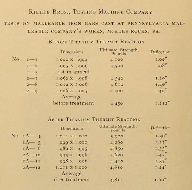
Some experiments, thanks to our fellow-member's, Dr. Moldenke's, kind intercession, were made at the Pennsylvania Malleable Works, with the foregoing results, the bars having been poured out of the same ladles, one before, the other after, the titanium Thermit reaction.
Experiments with lower grades of iron showed the same favorable results. At the Featherstonc Foundry, Chicago, titan Thermit treated test bars showed a tensile strength of 3,550 Pounds (15.8 kN), against average untreated, 3,250 Pounds (14.5 kN). The metal, after treating, is much denser, but can be easily machined.
Incidentally it may be mentioncd that by the introduction of a 1½-pound (750 g) cartridge of ordinary black Thermit into an 800 pound (400 kg) ladle 40 pounds (20 kg) of steel borings can be
melted without difficulty.
This necessarily very short account of what is doing in Thermit cannot, of course, cover the entire field of the applications, but will perhaps tend to convince those who had rather be guided by
results obtained elsewhere than spend time and money for what they think experiments, and encourage others who are doubtful from lack of experience, by showing them what has been accomplished in
actual practice.
References
- Ernest Stütz: The Thermit Process in American Practice. Read at the June, 1905, meeting of the American Society for Testing Materials. In: The Iron and Steel Magazine, September 1905, p. 212-221.