
Linear Friction Welding


Linear Friction Welding (LFW) has been established since the 1980ies as a niche welding process, where the work pieces are pressed against each other and moved forward and backward by ± 3 mm with a reciprocating motion of approximately 50 Hz.

The process is mainly used by the aerospace industry, for instance to make the titanium blisks (bladed discs) of the Eurofighter. Das Verfahren wird vor allem in der Luft- und Raumfahrtindustrie eingesetzt.
Linear Friction Welding of Aerospace Components
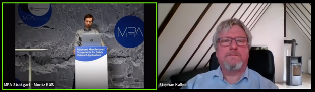
'Linear Friction Welding of Aerospace Components' at MPA Workshop on 'Advanced Manufactured Components for Safety Relevant Applications'
(Please click onto the yellow picture above, to open the ½ hour long YouTube video)
33:29 min, © Alustir, 12 October 2022
In this video, Stephan Kallee talks about linear friction welding of aerospace components:
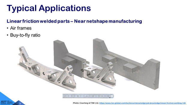
“I want to focus on nine topics on linear friction welding of aerospace components. Linear friction welding is a process that's increasingly been used for near-net-shape manufacturing. It's an advanced manufacturing process – not additive manufacturing, but adding little blocks to aerospace parts and then machining them to the final shape.
First I want to focus on the principal materials and applications and then on the motion machine and quality and finally on the design variants. I will conclude with the benefits and limitations of linear friction welding. It works in a way that you rotate or you oscillate two parts against each other. So it's similar to rotary friction welding, but it can be used for rectangular parts.
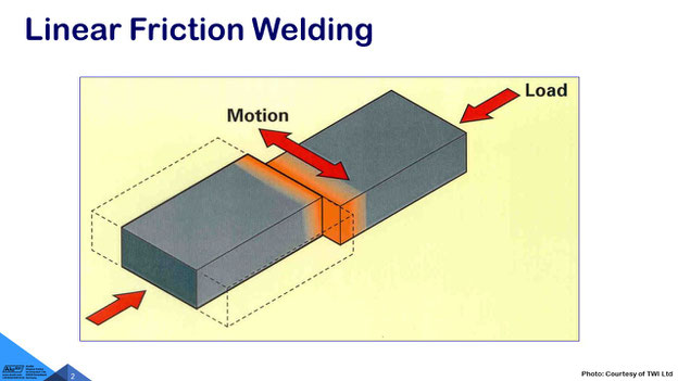
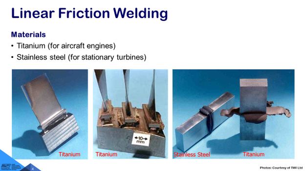
Fortunately, I have some parts here, but I can't really show them that easily in the online lecture. The idea is, that we produce pre-manufactured parts from various materials for example from titanium, like the blades that are made from titanium or from stainless steel. These are made by applying a reciprocating motion, while pressing the parts together with a very high force. You see some titanium being welded from the left to right: After the initial contact a flash or burr is being expelled, and finally the material cools down.
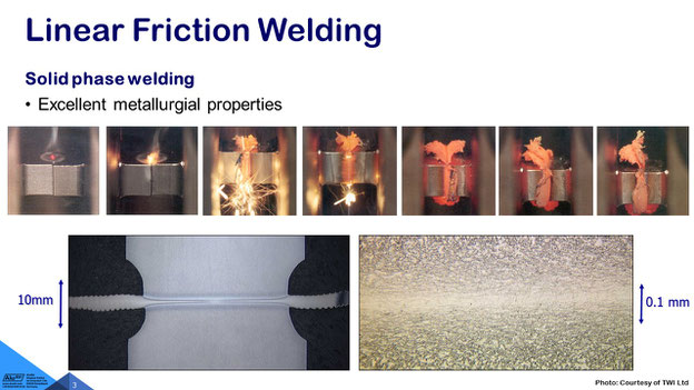
The big advantage of the the solid phase welding process is, that we do not melt the materials. We stay below the melting point of the materials and we don't even need to apply gas shielding, even in the case of titanium. As you see, we can see get a very nice microstructure.
The limitation is, that there is a still a flash or burr on the left and right hand side of the weld that needs to be machined off after welding. It's a process that is very stable and it’s used by all aircraft manufacturers. It's a very effective process indeed. The process can also be used for aluminium.
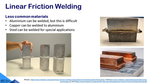
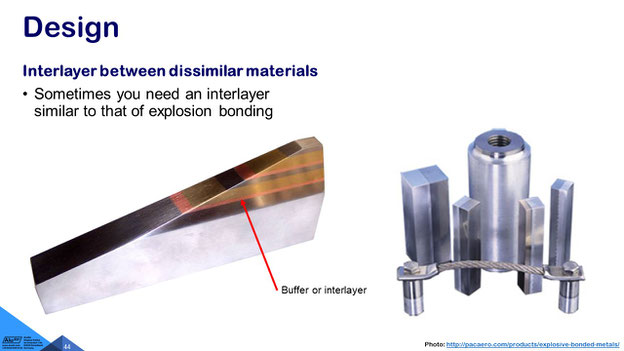
In the case of titanium you have a very low heat conductivity, so the heat really stays in the area that we want to process. In the case of aluminum it's more difficult, because the heat is being sucked into the workpieces. So you need really clever parameters and you get a wide flash. It is possible, to weld dissimilar materials for example welding copper to aluminium and it is certainly possible to weld steel in the automotive industry.
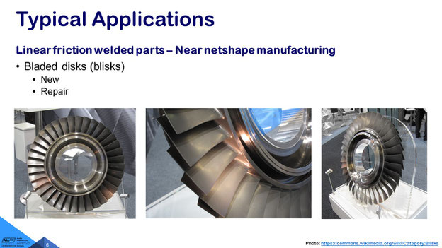
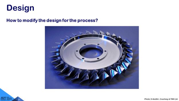
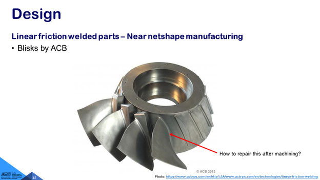
However, the main applications are due to the cost of the material in the manufacture of titanium components and that is what I want to focus on today. These are bladed discs or so-called blisks, either in the initial manufacture to save material instead of machining from solid, we machine a pre-manufactured near-net-shape part and then we machine it to the final shape.
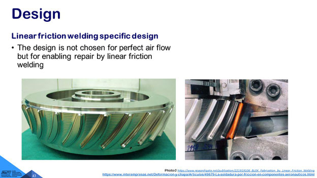
What you can see here, is the aero-engine fan blade of the blisk of a Euro Fighter engine. The typical applications are in the military aircraft, and I have to tell you, the shape of the blade is not perfect for aerodynamics. It’s a compromise between the possibility of repairing that product by linear friction welding and the optimized airstream of the part. So at the bottom of the blade, where the blade joins the disk, it's a little bit wider than as it would be absolutely necessary, but we will focus on that on the design stages later.
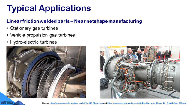
Whenever you try to get the process implemented by the stationary gas turbine manufacturers, who use very specific stainless steels and these are expensive as well. However, they don't see the cost advantage as significantly as the titanium users, so I'm not aware of stainless steels being welded in the stationary turbine business, but as you know with these very expensive and very complicated processes, you don't talk broadly about, what you do. So for example, it's an ideal process for repairing blades.
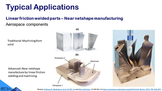
We want to focus on near-net-shape manufacturing or advanced manufacturing. What you see on the right-hand side, is machining a turbine blade from solid. So quite a lot of swarf is being generated. That material can be recycled, but it does not have the original value, and we see also that it's time consuming, to machine off these large amounts of titanium.
In the top picture, number (a), you see the machining from solid, and a little block is used and then for example a little fan blade is um being machined, but what we propose and what is being used now, is in number (b) at the bottom and we want to weld a block bilinear friction welding to workpiece number one, and then finally, we machine the part to the shape or the dimensions that are required and by that we first of all get rid of the flash, and we get rid of any kissing bonds, which are unwelded regions at the edges of the work piece and we have finally a part that needs our specification.
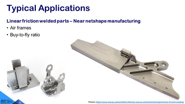
Here you see an aerospace part on the right-hand side that has been made from three components and even little blocks onto the substrate and then finally we machine this little bracket or tab out of the component in the weld integrity is so high that it is nearly not possible to distinguish it from the parent material. So we have a very refined microstructure and very high strength. So in titanium, there is no significant decrease of strength in the weld area.
The main purpose is to improve our buy to fly ratio – so how much material do you have to buy and how much is being machined off during machining, i.e. how much swarf is being generated during high-speed CNC, and then you need to check the weight of what will finally fly in the aircraft. That is the buy-to-fly ratio.
Here a similar component, I think you can see by now, this is the little block that was twice as large has been welded to the substrate and then finally machined off. You see here the burr or the flash being generated and that needs to be machined off, otherwise it would be a stress raiser for fatigue properties. With the exception of some simple automotive applications and the burr or flash is normally being machined off.
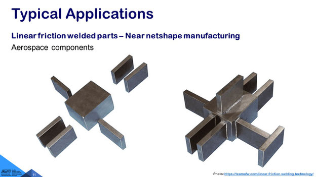
Here we see a part that consists out of I think it I counted it was 11 parts. On the right hand side you'll see all of the 11 parts. I think you understand the concept by now. So it's a reciprocating motion, where the smaller parts are being vibrated against a stationary part. The part in the middle is kept stationary, and they are pressed with a high force onto the work piece.
Why do we need the high forces? In solid phase welding, we want to stay below the melting point of the material, and by that it's more like a forging process. It's more like a process, where you like making the Damascene steel and the swords, by forge welding, or fire welding, where material just gets hot, and at the end of the cycle (we will come to that in a second) we will increase the pressure to get all this plasticized material pressed into the flash or burr.

Here you see some rocket fuel tanks made at TWI, The Welding Institute in Cambridge, England. These are made from titanium and typically this is a very large dome for example which needs to be bolted to another aircraft structure. So here you see the bolt holes, and to make that, we use linear friction welding very effectively, to process titanium parts.
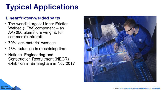
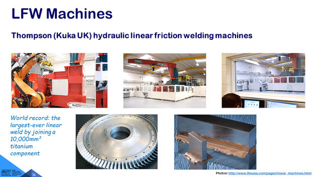
The largest linear friction welded part or component was a near-net shape component, and you see the figures here: very little material wastage, the machining time has been reduced, and we were able although this seems to be similar to military components in military aircraft we were able to exhibit that in Birmingham but indeed the military aircraft industry is the one that use the process the most for near-net-shape manufacturing, and they don't talk about, what they really use it for, but for similar components, like the ones shown here.
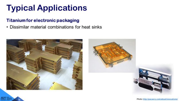
I have an idea, to use it also for titanium heat exchangers. So, in some hot areas, titanium is the material that you choose. I'm speaking also about the glass conduction for example, how to get the cables through these parts. That's big business and instead of attaching with a rubber seal a little lid, you could easily use linear friction welding, to attach the lid to the heat exchanger.
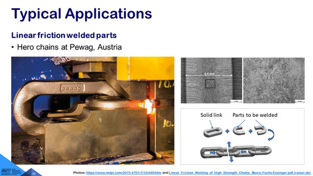
Not in the aerospace business but in the manufacture of chains in Austria, in Styria, a company called Pewag uses the process to make links of heavy duty chains, for example for snow chains in the smallest area that they do, but they do larger chains as well, and you see, they have two different type of links: The solid link is a complete part that is forged, and then, there are parts that are made from two half parts to be welded by linear friction welding. I could introduce you to Pewag, a very interesting application, and this is the unusual thing, they use it for steel.
Another steel application is making new wheel rims for agricultural vehicles or excavators, where the big bub of the wheels is being linear friction welded at the top.
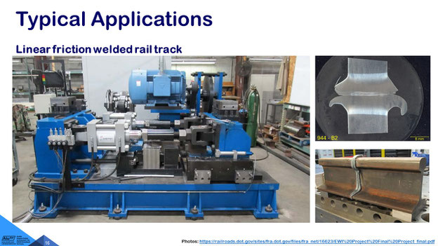
A dream coming true is going-on in America at our friends at Edison Welding Institute (Jerry Gould). This is instead of using flash butt welding, which has advantages and limitations, using linear friction welding for making rails instead of using thermite welding either in the factory, to make long rails that cannot be made in one part and then transport them onto site, and endless rails to be made in the factory as shown here, but ideally, even with a portable machine to be done on the construction site, to join the high-speed rails.
I have had a good look at this machine, and we will see later-on, how the principle in general looks, but here we have a mechanically driven machine so the oscillation is done by a large electrical motor and a flywheel, and only the pressure is applied by hydraulic actuation.
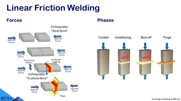
What type of forces are necessary? You see here the up-and-down movement or forward-and-backward movement, that is what we call the in-plane force, by which reciprocal motion is being generated. We need a relative motion between one stationary part on the right and one vibrating or reciprocating part on the left, and then we have the axial force, and that goes up to a region of 150 tons in typical commercial applications, so the blue railway rail track welding machine that is a machine with 150 tons.
So, you see four different phases: The initial contact phase where the material just gets hot by friction and then conditioning, so the spikes of the material have already been worn-out, and now we have a sliding contact with the in the burn-off phase with a plasticized layer in between. The flash is being generated, and then we stop the reciprocating motion. You see the red arrow disappears, and the two parts are carefully aligned against each other, and the forging force is applied, which is typically at least 20 or even 50 percent higher than what we use during the reciprocation.
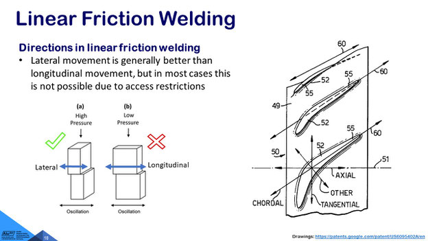
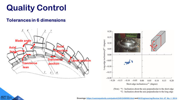
There are two different concepts of motion possible: You see here on the left-hand side, that is the recommended movement. The lateral movement over the short edge of the part, and the longitudinal motion is not really ideal for having perfect metallurgical properties but in some cases, it cannot be done differently for example if you have access difficulties like on these turbines, there you use typically, what they call then the chordal movement along the long axis other ideas would be to use a tangential or a perpendicular movement. So there's a lot of know-how and, you see, even patents involved in having the right choice here.
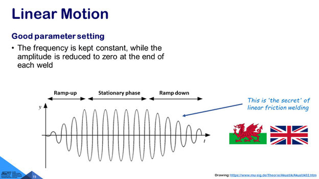
You see two flags, and the dragon is representing Wales. The Welshmen Dave Nicholas and Wayne Thomas were at TWI, The Welding Institute, the leading investigators in getting the metallurgy and the parameters right on friction welding, and on the right-hand side you'll see Edward Watts, a very capable technician, who operated the machine. The machine has been manufactured by Black's Equipment, a company that focused on supplying the coal industry, initially, and then focused on the rotary friction welding and linear friction welding and transferred the know-how then to Thompson, what is part of Kuka UK and the Thompson friction welding machine.
But the most important thing that you learn today is the secret of being a friction building has been divulged today. The secret is that you do not reduce the frequency at the end of the weld, but you ramp-down the amplitude. So the movement gets from plus and minus five millimetre, plus or minus four, plus and minus three, plus minus two, plus minus one, to plus and minus zero. That is the way, how you can align the components so well against each other.
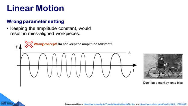
That is difficult. You need a special gearbox, to do that. It's not like the ‘monkey on the bike’. The ‘monkey on the bike’ is at the end of his trip with the pedal somewhere in the space, and that's the wrong approach. It will never work, to get parts properly aligned.
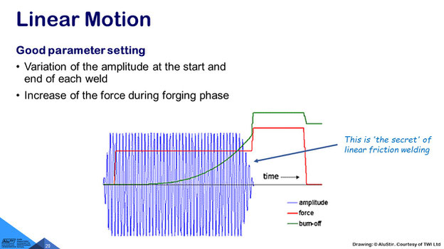
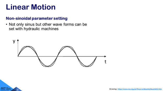
This is a real sketch of amplitudes in blue, forces in red and burn-off in green being mentioned. Burn-off that is the material that is being expelled into the flash or burr. Burn-off means, we measure, how much shorter has the part become, so we need to look at that, and here you see, that the force, in this case the red curve, has been significantly increased at the end, when the parts are stationary, … when the amplitude has been ramped down, and then we generate most … in that phase at the very end, in which we increase the forging force at the end of the weld.
I was privileged, to be the project leader of a large … European funded project on doing non-sinoidal motion. So, with the mechanical system, like ‘the monkey on the bike’, you can only do a sinus-wave, but we wanted to start having hydraulic actuation. First of all, for cost saving and, second of all, to have … a more versatile system, where different type of modes could be driven.
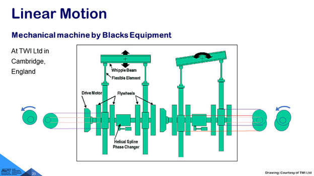
But let us focus first on the mechanical systems that have been built. This is a complicated gearbox, and on the left-hand side, we see the linear motion being generated, so plus and minus, let's say, three millimetres of amplitude and on the right-hand side we see that beam only swivels around that pivot point. So, this pivot point does not move up and down anymore, and to achieve that, this goes really to a zero at the end of the weld cycle, we just use two excentres on the same shaft, which is driven by an electrical motor from the side, and if you align them in a way that they are misaligned then they be in the swivels and if they are in phase, and then being rotated, as shown here in the left-hand picture, then this whipple pin moves up and down or forward and backward. The British idea was, to use instead of using bearings, that could wear out, to use a flexible element like a blade, and as far as I remember, only one of these blades has ever broken, so that was so well designed that the whole machine was fully balanced, and you could put a coin, standing on its edge, on top of the machine, without the coin tipping over during the process.
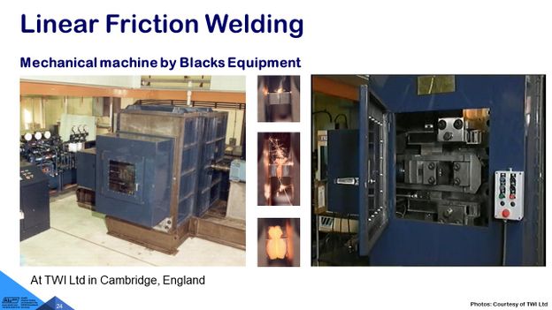
Here you see the electrical motor that drives this electrical system, and hydraulics involved in applying the forging force the in-plane force in the joint area. That is being generated by electrical means. It's a noise proof cell. In this case, the machine is not on rubber elements decoupled from the floor, but it generates by some vibration, and I had my office just above that machine, you didn't need to ask, which customer’s products were just being processed, so you could just hear from the welding cycle, what type of material was being processed, or you knew, of course, in the background, which parts were then made. So, we did a lot of prototyping parts that have been then assessed by the clients.
It was big business at the time, just producing metallic combinations of different types, to check, whether this process could be used in the aero-engine manufacture. There were only three machines being sold worldwide of this mechanical concept, and one of these Black’s Equipment machines is at MTU in Munich, … and one of them is at TWI and the third is at Rolls-Royce. So these were only three machines, because they had an investment value of, let's say, some over 3 million Pound, or nearly 5 million Euro with all the tooling that goes with them.
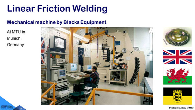
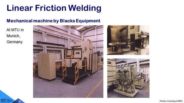
So here you see for example the machine at MTU, and that has been built by Black's Equipment, and you see the flags in the background and there's a Stuttgart flag (and this is not for MPA, I have to say), and this is for Rudolf Reinhardt of Mercedes-Benz, who provided knowledge on rotary friction welding and fixturing, and the tooling that you see here, that is, if you see that once, not everybody can access that room, this is really impressive stuff, and then we see the Welsh dragon for Dave Nicholas and we see the Union Jack for Roger Black. This was a very nice collaboration, in the, I would say, late 70s, early 80s, when linear friction welding has been transferred from the United Kingdom to Germany.
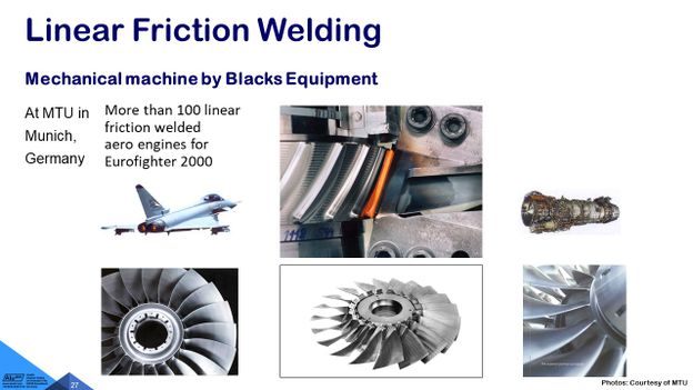
And MTU was in a delightful position, to produce the fan blades of the Euro Fighter aircraft. You see again these little blocks which are necessary for clamping the parts and more than 100 linear friction welded engines were being built, so this did not go in very high volumes, but of course there are many blades on one disc, and all that with the mechanical machine.
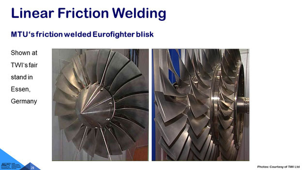
Quite an impressive activity at the time, and they were very proud about it and published that very well, so these are the ‘blisks’, the linear friction welded blades to disk combinations that TWI was then exhibiting at one of the fair stands. As an admiration for the work that we had provided, we got some very nice samples to be shown.
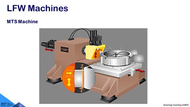
The Americans had a different approach: at MTS, it's an hydraulic manufacturer of fatigue testing machines, they thought, we do that hydraulically, and my boss Dave Nicholas had the idea, how this would generate some cost savings, if we use a linear friction welding machine, and we produced the LinFric® machine within this European funded project in collaboration for example with Black’s Equipment designing the machine, Raiser in Germany making the machine frame, ZwickRoell in Germany and England making the hydraulic oscillator, Harms & Wende making the control box and Deltamatic in Italy making the tooling. So this was a good one, of the very first European Projects that started in ECU with 1.36 million ECU which is similar to a Euro at the later stage.
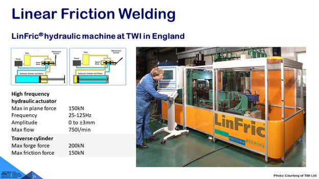
What you see in the background is a hydraulic accumulator. So similar, to storing electrical energy in a capacitor, we have a hydraulic system that compresses a rubber bladder like an air balloon inside these vessels, and so we need some, let's say, maybe two or three minutes to charge-up the hydraulic system, and then we have an oil flow of 750 litres per minute for the duration of the weld. This is a very energy-saving system being implemented, with this energy storage system, similar to a mechanical flywheel, we use a hydraulic accumulator.
And at the time, this was the biggest machine of the world: 150 kN, that's still a big thing, and you see, you could, instead of having this green bar here, … you could install a complete aero-engine with approximately a meter diameter instead of using this green part, which is not part of the machine. That is just a temporary fixture for making smaller type components. By the way, this is me on the left-hand side in younger years working still hard, it was a tough life.
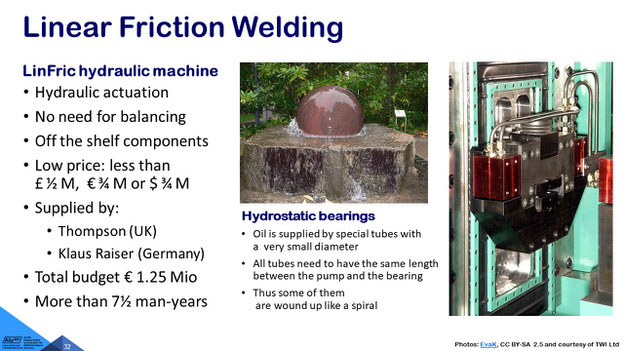
But the idea of this machine was, we used hydrostatic bearing. Here you see the fountain in Frankfurt Palmengarten, and you see that marble ball can flow very easily, you can operate it by hand, and it rotates itself, and we adopted the same system. So we have very tiny little tubes, through which we feed-in oil into. This is a rubber element made from an old tire, I would say, or similar to an old tire, so we have a system, where are friction is being minimized by using these type of hydrostatic bearings.
The total budget … of the machines was thinking that we wanted to sell them for 750 million Euro, and we spent some seven and a half Men years just to develop the prototype. The prototype worked on occasions very well, but it has then had some complex challenges regarding hydraulics and control system, and then Thompson built a replica of that part and that is being used now at TWI on a day-by-day basis. Thompson industrialized that to the next level from prototype to industrial machine.
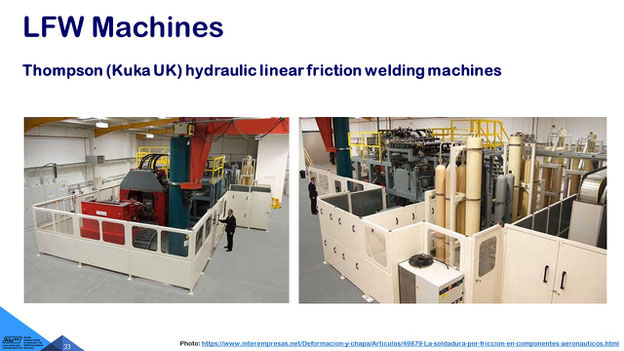
These are the Thompson machines. That would be interesting, to hear about the history of what they learned out of the experience with linear friction welding. I know what they think about it, and large parts have been made, and I can introduce you to the relevant parties, if you ever want.
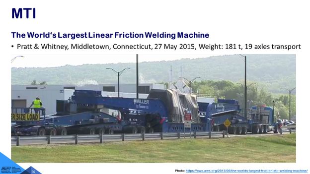
You know, in the United States, everything is a bit bigger. This is a 19 axles transport, the total weight of the machine is 181 t, not everything is on the same truck. There are, I think, some 10 trucks have been transported to get this machine this is only the machine bed on the on the low-loader. The total weight of the machine is 181 t at Pratt and Whitney.
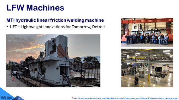
A similar machine is now at LIFT in Detroit – very big machine beds, and they are of course put into the floor. Again, I have access to that machine, if you need some prototypes, I will establish the contacts.
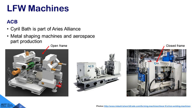
One of the most interested users, who speaks very little about it, is a company in France, and that is supplied by ACB (Aries Cyril Bath), and they have two different type of hydraulic machines: Here is the open frame machine, and with a significant benefit of loading that by crane, and then we have a machine with a closed frame at the right-hand side.
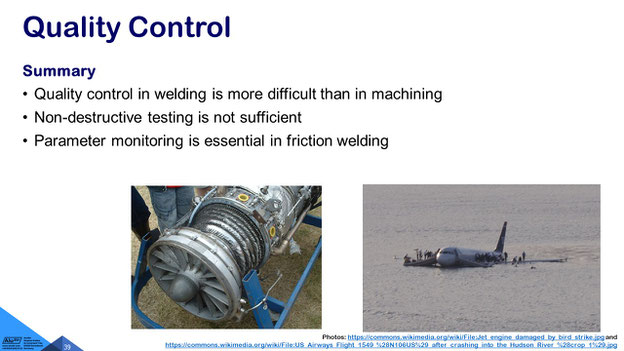
The Chinese are following up again with the concept that I have demonstrated with the hydraulic actuation, and the most important thing is, you need to think, what happens, if something goes wrong, so for instance bird strikes you remember that situation on the Hudson River in New York (edit: not Washington DC), so then you can do repair.
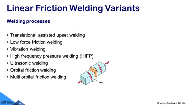
And, only quickly, I want to look at the variance, and you can look into the proceedings later, but orbital friction welding is a good one.
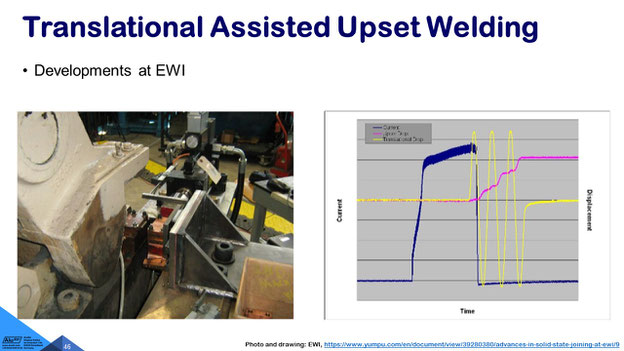
Translational assisted upset welding, where an electrical current is being used, and only one, two, three, four, five, six cycles are used at the end, to disrupt the oxides. That's the trick: The oxides are being disrupted by the friction.
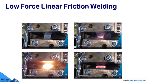
Low force linear friction welding, again, applying some electrical energy in addition to the frictional heat.
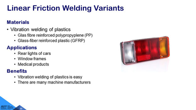
Very common for welding plastics for example the different colours of a rear light of a car.
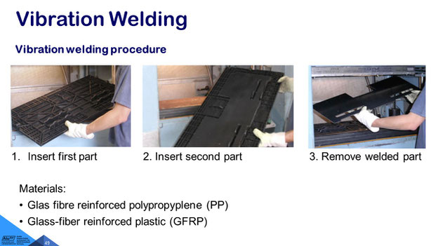
Vibration welding of glas fibre reinforced polypropyplene (PP), glass-fiber reinforced plastic (GFRP) or other automotive materials, e.g. in automotive air duct systems.
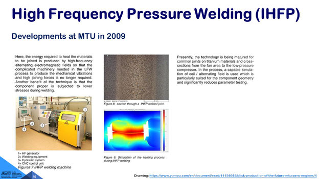
High frequency pressure welding, have a look at that.
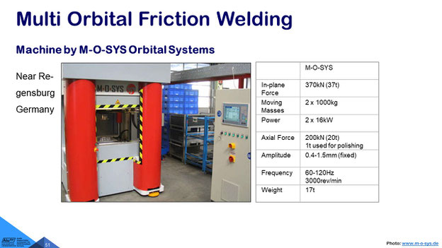
A system for making window frames Multi Orbital Friction Systems (in Runding) near Regensburg or Nuremberg.
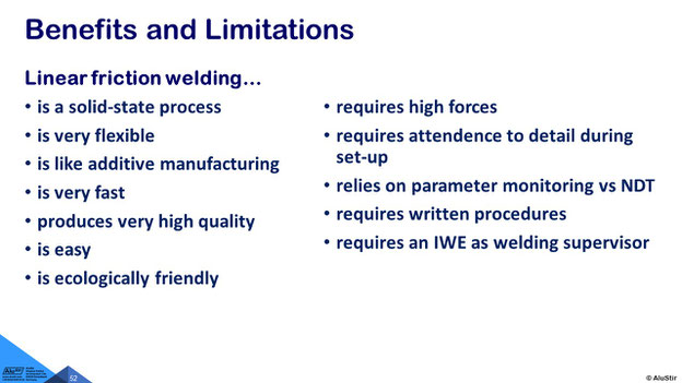
And, just to summarize the benefits and limitations, I want to show:
- it's a solid phase welding process
- it's very flexible
- it's used for near-net-shape manufacturing
- it's easy and ecologically very friendly,
- however, it requires some high forces and you need to set-up the parts very carefully
- it mainly relies on parameter monitoring, so this is not the activity of MPA, to look at the welded parts, you need to monitor during welding, whether the parameters have been met and then you know that you have the good quality
- it requires some written welding procedures and, ideally, a European welding engineer to supervise the welding activities
And, I think, I'm just in time, thank you very much for your interest and I'm looking forward to discussions.
Thank you Mr Kallee for this very interesting talk about an interesting topic. Are there any questions from the participants so I don't see a raised hand. Okay, I'm going to ask you one thing, and maybe you um already explained it in with your last slides, but when you showed the examples in the beginning, where you first made the welds and then the machining after, and I had the question, if you always do it this way, or the other way also, so you first machine the parts to the final contour and then do your welds, so you have both possibilities or what is recommended?
Most commonly a machining process follows the welding process, because at least you want to remove the flash or burr. I know in some rotary friction welding applications, in automotive applications, like for example airbags, you can't remove the flash, so the flash will stay inside the part, and so sometimes maybe the flash stays on the inside and, of course, we have sometimes hollow blades as well. In most cases a machining process follows, and if a machining process follows, then you have even this near-net-shape manufacturing that you have an area that can be more easily clamped. I don't know anything where no machining would be necessary after welding.
Okay thanks for this explanation, … so thank you again Mr Kallee.
LinFric®-Linear Friction Welding Machines
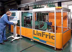
We have developed a hydraulic linear friction welding machine within the European LinFric®-Project (www.linfric.com). Even steel can be welded with this machine, for instance to make wheel rims of off-road vehicles. The main applications are, however, in the production of stationary turbines and Jet engines als well as the manufacture of near-net-shape parts by the aerospace industry.
The concept has been developed and proven in a collaborative project with eight European partners. The experiences and contributions of the individual partners were exploited very effectively.
The benefits of the hydraulic LinFric® machines are based o the innovative way to generate the oszillating motion in comparison to mechanically driven machines, which use a complicated gear box. Their heart is a hydraulic oscillator, which vibrates at a frequency of 25-125 Hz, an amplitude of up to 3 mm at an oil flow of up to 950 l/min. The maximum forging forces is 200 kN (20 t) so that cross sections of upe to 2000 mm² can be welded in steel. The hydraulic oscillator can provide both sinusoidal and non-sinusoidal motions, which is useful for some of the materials to be welded.[1]
MTI Machine at Pratt & Whitney
A hydraulic MTI linear friction welding machine produced by MTI was delivered to Pratt & Whitney in Middletown, Connecticut on 27 May 2015. I has a weight of 181 t (400,000 lbs), so that a 19 axle special transport was required.[2]
It can be used for linear friction welding of critical aircraft engine components to support Pratt & Whitney’s most advanced military programs and advanced products.[3]
AVIC Linear Friction Welding Machine
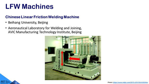
A similar hydraulic linear friction welding , designated LFW-20T, was test was developed and home-made at AVIC Manufacturing Technology Institute, Beijing, China. The machine can for instance be used at 3 mm amplitude, 50 Hz frequency and 15 t friction pressure for The size of TC17 titanium alloy samples with 20 mm (Z) × 75 mm (Y) × 120 mm (X), where Y is the vibration direction, X is the direction of friction pressure, and thus a friction surface of 20 mm (Z) × 75 mm (Y).[4]
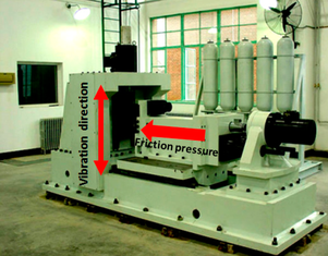
AVIC'S 20 t linear friction welding machine LFW-20T
© Xiaohong Li Jianchao He, Yajuan Ji, Tiancang Zhang and Yanhua Zhang, CC BY 4.0
Publications on Linear Friction Welding
-
Friction Welding of Aero Engine Components. 10th
World Conference on Titanium Ti-2003, Hamburg, Germany, 13-18 July 2003.
-
The World’s Largest Friction (…) Welding Machine. 3 June 2015.
-
MTI ships
2-story-tall jet engine machine.
- Yanhua Zhang, Xiaohong Li (School of Mechanical Engineering and Automation, Beihang University, Beijing 100191, China) Jianchao He, Yajuan Ji and Tiancang Zhang (Aeronautical Key Laboratory for Welding and Joining Technologies, AVIC Manufacturing Technology Institute, Beijing, China): Study of the Microstructure and Fracture Toughness of TC17 Titanium Alloy Linear Friction Welding Joint. Metals 2019, 9(4), 430, CC BY 4.0. Published: 11 April 2019.