
THPD Control during FSW

How Deep Should the FSW Tool be Plunged during Friction Stir Welding?
Visual control during friction stir welding (FSW) is one of the most effective means for achieving high-quality welds. As a rule of thumb, 75-95 % of the tool shoulder circumference should be surrounded by plasticised material, if the tool is tilted by 2.5°.
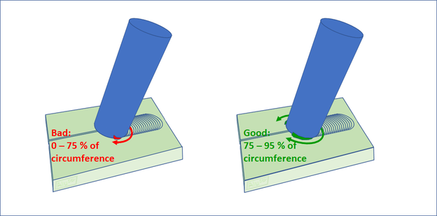
Plasticised material should surround 75 – 95 % of the friction stir welding tool shoulder, if the tool is tilted by 2.5° (an exaggerated tilt angle is shown in the sketch)
© AluStir
The tool heel plunge depth (THPD) should be pre-set, as shown on the page page "FSW: Tool Heel Plunge Depth - How to Set the Pin Length and Tool Heel Plunge Depth for Friction Stir Welding?". Even so, experienced friction stir welders keep an eye on the amount of plasticised material that is visible underneath the shoulder in front of the FSW tool pin. At least 75 % of the circumference of the FSW tool shoulder should be surrounded by plasticised material. Otherwise, the pin can be seen, if you look from a very low angle along the weld line.
Many FSW machines, especially those used for aerospace applications have a camera installed before the FSW tool, to observe the amount of plasticised material on a computer screen and to store a video on a hard disk for quality control, i.e. to demonstrate to the management and/or to the customer that the tool has been appropriately set during welding. In future, in-line automated image processing might be used for assessing the video images and adjusting the tool heel plunge depth, while the weld is running. Appropriate algorithms could be developed in the aiCAMstir project.
In the case of manually operated conventional milling machines the tool heel plunge depth can be manually adjusted easily, while the weld is running. Most CNC controlled FSW machines have a human-machine-interface, with which the height of the tool or the force can be adjusted, while running a weld. If such features are not available on CNC milling machines, the weld needs to be aborted, the end hole filled, e.g. by MIG welding and then a new weld should be made with improved settings. In some cases for the second weld, a larger tool is plunged in the existing end hole, i.e. a tool that has both a larger diameter pin and a larger diameter shoulder, which rotates at a lower rotation speed and is traversed at a lower welding speed. Retracting the tool and plunging it into the same end hole again can cause welding defects in the stop/start region.
Visual control of the tool height is more difficult, if the FSW tool is not tilted, but kept perpendicular to the weld surface. This requires a scrolled profile on the tool shoulder and in most cases a CNC controlled machine.
Please contact stephan.kallee@alustir.com if you need help on controlling the tool heel plunge depth during friction stir welding.