
Thermal Stir Welding (TSW)

A rotating pin between two stationary shoulders to join preheated workpieces
Thermal stir welding is an unusual solid phase welding process that was patented and developed at NASA's Marshall Space Flight Center to improve upon fusion welding and friction stir welding.
It is basically a rotating pin between two stationary shoulders to disrupt the oxides between two preheated workpieces.
From the drawing in the patent application it is difficult to understand, how the process works, but an entry in the Machinery & Equipment section produced by Tech Briefs shows a CAD model of the "stir rod, containment plates and induction coil."[1]
Thermal stir welding can be applied to flat plates or to corner sections, as shown in the hexagonal demonstrator specimen, which was made from 6Al-4V titanium (ELI) plates. It contains six angled thermal stir welds at the corners and six flat plate thermal stir welds at the faces.[1]
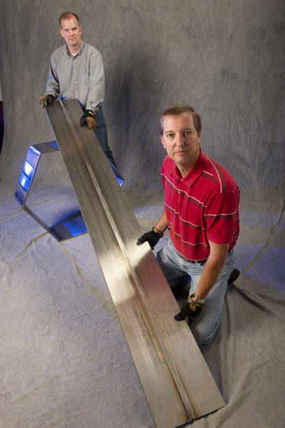
A 2,75 m (9 ft) long butt weld and a hexagon that were fabricated from 6Al-4V titanium (ELI) using thermal stir welding within a project for one of NASA'S technology transfer industrial partners Keystone Synergetic Enterprises, Inc. in support of a project for the U.S. Navy by André Paseur (Weld Technician, Jacobs ESTS Group/ERC) and behind him Samuel Smith (Weld Technician, Jacobs ESTS Group/All Points) in September 2010.
© NASA, No 1001619
Thermal Stir Welding is a hybrid of conventional friction stir welding in combination with induction heating, ultrasonic welding and/or fusion welding. It is an innovative alternative to conventional fusion welding and friction stir
welding technologies. It is possible to join similar or dissimilar materials at high speed, because additional heat is supplied by the preheating or melting mechanism.[2][3][4]
Benefits
• No backing bar (anvil) required
• Suitable for making corner joints
• Filler material can be added
• The hybrid processs is potentially better than fusion welding or friction stir welding
• Heating and stirring are seprated
• More variables to play with
• Improved surface finish results
• Can be put in a shielding gas box
• High welding speeds
• Additional heat input for welding alloys with higher melting temperatures, such as steel and inconel alloys
• Better microstructure than in fusion welding
Limitations
• Patented by NASA
• Limited amount of information available in the public domain
• Very limited industrial applications so far
• Complicated equipment required consisting of:
• very rigid machine,
• additional heat source
• computerized control algorithm
• More variables need to be controlled
• Melting occurs, if fusion welding heat sources are used
• Further R&D required
The hybrid process is better than fusion welding, if the microstructure of the work piece material and its physical properties are affected by heat as in many high-strength alloys. In some cases it might have benefits in comparison with conventional friction stir welding, where the heating and stirring functions depend on each other, when using the same rotation speed for shoulder and pin.
It is similar to Bobbin friction stir welding, because an “upper containment plate” and a “lower containment plate” are used. It is also similar to stationary shoulder friction stir welding, because the containment plates do not rotate in most cases.[2]
Angled welds can be made by thermal stir welding, because the non-rotating containment plates can be shaped to accommodate weld joints of different geometries. The angled welds at the corners of the hexagonal demonstrator piece shown in the photos required angled containment plates with a 120° angle. These angled containment plates pressed the plastised material into the joint line, while the rotating stir rod caused grinding, mixing and extrusion to improve the microstructure of the weld metal.[1]
In the case of welding flat plates, however, cylindrical containment plates can be used for thermal stir welding, and these can be rotated at a lower or higher speed in the same or in the opposite direction than the pin.

This hexagon was fabricated from 6Al-4V titanium (ELI) using thermal stir welding.
© NASA, No 1001624

The part contains 6 angled thermal stir welds and 6 flat plate thermal stir welds.
© NASA, No 1001623
The thermal stir process separates the characteristic heating, oxide disruption and forging processes of the conventional friction stir welding process. A fusion welding device (laser, plasma torch, etc.) can be used to temporarily melt the material. Alternatively a solid state pre-heating process such as induction resistance heating or resistance heating of the pin can be used.
If a fusion welding device is used to heat the material, the separate stirring action of the rotating pin refines and recrystallizes the resulting grain structure, while it solidifies and cools down. The heat input from the power source and from the rotating pin can be controlled independently, ideally using sensors and a computerised control algorithm.
Thermal stir welding does not requires no backing bar or anvil. The apparatus used for the weld process is enclosed in a main housing, which allows for the possibility of an inert or active gases in the melting compartment if needed.[2][4]
TFW of HAYNES® 230® alloy, a nickel-chromium-tungsten-molybdenum alloy
Phase I or a completed SBIR/STTR technology project on "Thermal Stir Welding of High Strength and High Temperature Alloys for Aerospace Applications" demonstrated in 2009-2010 the feasibility of thermal stir welding of high strength and high melting temperature alloys such as Haynes 230, which is of interest to the NASA for the upper stage engine, nozzle skirt on the ARES I and the ARES V heavy lift vehicle.
Potetnial non-NASA applications include solid-state welding of military and commercial gas turbine engine components.[6][7][8]
Patents
The invention was made by an employee of the United States Government and may be manufactured and used by or for the US Government for governmental purposes without the payment of any royalties.
- R. Jeffrey Ding (NASA, National Aeronautics and Space Administration): Thermal stir welding apparatus. US Patent No US7980449B2.
- R. Jeffrey Ding (NASA, National Aeronautics and Space Administration): Ultrasonically-assisted thermal stir welding system. US Patent No US8899467B1.
References
- Jeff Ding:
Thermal Stir Welding Process (including schematic drawing and photo of Nova-Tec G10K Machine). Tech Briefs, 19 June 2012.
-
Thermal Stir Welding - Solid State Welding Process.
-
Ultrasonic Stir Welding -
A new solid-state weld process for better weld quality and longer tool life.
- NASA Tech Briefs: Jeff Ding, Aerospace Welding Engineer at NASA Marshall Space Flight Center. 1 November 2009.
- Jeff Ding: NASA Welding Technologies Could Revolutionize Workboat Fabrication. 14 September
2018.
- HAYNES® 230® alloy
- Excellent High-Temperature Strength, Thermal Stability, and Environment Resistance.
-
Thermal Stir Welding of High Strength and High Temperature Alloys for Aerospace
Applications, Phase I. Completed STTR Technology Project (2009 - 2010).
- Bryant H. Walker (Keystone Synergistic Enterprises of Port Saint Lucie, FL): Proposal No. T9.01-9919 – Thermal Stir Welding of High Strength and High Temperature Alloys for Aerospace Applications.