


One of the First Impartial Publications on Aluminothermic Welding in America
The thermit process generates by aluminothermic reactions heat for thermit welding and similar processes. One of the first impartial scientific publications about this process and its practical applications in the U.S.A. was published by Richard N. Hart in 1910 in his book on Welding Theory, Practice, Apparatus and Tests, as shown below:
The Thermit Process
By Richard N. Hart, B. S.
Published in: Welding Theory, Practice, Apparatus and Tests
Electric, Thermit and Hot-Flame Processes [1]
General
One of the most recent and successful methods of welding is called the Thermit Process. It was invented by Dr. Goldschmidt, of Essen, Germany, and is exploited by the company bearing his name. In
this process a mixture of aluminum and oxid of iron is ignited. The aluminum reduces the iron from its oxid, and evolves an intense heat, about 2500° C, or twice the temperature of molten
steel.
This molten steel, called thermit steel, is then poured around the metal to be welded and forms a melt-joint that is very strong when cold. Its present application is entirely in repairs of large
metal pieces and in making continuous welded railroad track. It is used in repair shops for mending car axles, auto and electric motor cases, broken and defective castings, broken parts of
reciprocating engines, broken rudder-posts, skegs, and sternposts of ships, and for repair work in general along this line.

Fig. 62. — Finished thermit weld of S. S. 'Betsy Ann' before removing metal left in gate and riser. [2]
Special thermit mixtures are being advocated for toning up the melted steel in the ladle in foundry practice, for preventing "piping" of ingots; and the company is using the strong reducing
property of aluminum in reducing a number of the less used metals, such as tungsten, chromium, and boron, to a pure metallic state.
Thermit is first of all a welding process. Its good and weak points may be summed up thus:
- Simplicity of the apparatus.
- No special skill needed to do the work.
- Possibility of repairing breaks difficult of access and of repairing parts in situ that would otherwise have to be taken out.
- Possiblity of intense local heating of large parts.
- Time and money saved in most repair work.
- Possibility of varying the chemical composition of thermit steel so that its properties may be varied.
- It is at present limited to rail welding and repair work.
- Only iron and steel can be welded.
- The cost, though much lower than the forge method of welding, is still often prohibitive.
The process is used by many of the leading railroads, shipyards (Fig. 62), and machine shops of all of these countries, both for repair work and for special jointing, such as that of the third rail of the Paris subway.
At present Dr. Goldschmidt is trying to produce chemically pure metals on a commercial scale. He has met with success in reducing metallic manganese, chromium, tungsten, vanadium, molybdinum, boron, etc., from their ores and oxids.
This new field in metallurgy, now called aluminothermics, seems to promise as many new and interesting possibilities on its horizon as did the experiments of Moissan with his electric
furnace.
The fundamental idea beneath thermit has been in the minds of metallurgists for at least a half-century. In the year 1869, a Mr. Budd[3]
describes a process for reducing the alloyed silicon in pig iron. His idea was to burn it out with hematite ore, the formula being:
3Si + 2Fe2O3
= 4Fe + 3SiO2.
He made a paste of hematite and smeared it over the bottoms of the pig molds. The molten iron, which appears to have been much too high in silicon, was run into the molds, and immediately the silicon began to burn out of the iron, first taking up the oxygen of the hematite mud on the bottom of the mold, and then uniting with some of the iron and coming to the top as a silicate-of-iron slag. Most of the iron reduced from the hematite added itself to the pig. Like the Goldschmidt method, this was the reduction of one metal by the transfer of its oxygen to another metal.
The fact that aluminum has the greatest affinity for oxygen has long suggested it as a final reducing agent. And its steady fall in price since its discovery by Woehler in 1857 finally brought
it, about 1895, within range of the market. Woehler himself tried to smelt chromium from its chlorid by ignition with metallic aluminum. After an explosively violent reaction, he found he had an
alloy of chromium with aluminum.
A number of later attempts were made to use aluminum as an agent for reducing the rare metals from their oxids. Yet, though it had an intense affinity for oxygen, the combustion was hard to
start, and when started was hard to control. Experimenters mixed it as a powder with a metallic oxid and heated the mixture from the outside. Finely divided metallic aluminum will not burn at the
temperature of molten cast iron. So that when the contents of the crucible began to react, the initial temperature was already so high that the reaction was an explosion. Dr. Goldschmidt overcame
this by setting off the cold powder with a fuse of barium peroxid, BaO, which in turn was set off by a storm match. A charge of several pounds was found to burn in less than 30 seconds, and the
temperature of the mass rose to an approximate 2500° C. Larger quantities, though starting to burn from a cold and coarsely powdered sand, often boiled over. A premixture of cold steel turnings
remedied this. The result of the burning was an intensely hot iron whose composition could be varied at will.
The commercial value of this invention is obvious. There are many processes and many emergencies where a very hot molten iron is invaluable, yet where it is difficult and expensive to get this
heat by any known means. Take the case of a broken casting of some large machine that would in the ordinary course of repair have to be taken apart and shipped to the nearest forge to be welded.
If, however, a definite quantity of iron, heated to twice its melting point, can be made on the spot, it can be poured around this break without dismantling the machine. It will then form a
welded union, much as though one were to put the butts of two candles together and pour hot tallow over the joint. The tallow would melt into the candles before it itself cooled, and join the two
with a homogeneous substance.
In order that the mechanical aspect of the thermit weld may be clear to the reader, a simple case of rail welding will be outlined. After which the appliances used in the process will be
described in detail.
Apparatus and Rail Welding
Suppose a case of two rails abutting which are to be welded together. It is a railway crossing where heavy trains pound. The weld must be at least as strong as the rail. It must be so made as not to interfere with the travel of the wheels by coming up over the head of the rail.
First of all, the rail ends must be cleaned of oxid and grease with a sand blast or emery-paper or hydrochloric acid.
Next, the rail ends are heated to a dull red heat with a kerosene or, preferably, a gasoline torch. This merely assists the hot thermit metal and prevents a premature chilling of the thermit when
it is poured in the mold.
Two clay molds are next clamped on either side of the junction. The shape of the interior of these molds is, of course, determined by the shape of the collar which is intended to be cast. In this
case, as shown in figure 64, the collar should extend 2 inches (50.5 mm) over each rail end. It shall be twice as thick as the shank of the rail and also the base of the rail. It shall stop
short of the rail heads, which shall remain free. The mold is constructed so as to allow the molten metal to be introduced from the bottom, as shown in the figure. After coming in from the
runner, at the bottom, the slag and excess steel overflow into the riser.

Fig. 63. — Rails before welding.[4]
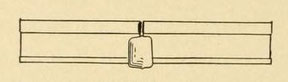
Fig. 64. — Welded rail, showing thermit-steel shoulder.
We have then two rails enclosed in a mold whose capacity, over the rails themselves, is known. To produce enough thermit steel to well fill this mold and to allow as much more to fill the runner
and the riser, take eighteen times as many ounces of thermit powder as there are cubic inches of surplus space in the mold.
The above amount is arrived at as follows: One cubic inch (16.4 cm³) of steel weighs 4 1/2 ounces (128 g). Four and one-half ounces steel is produced by twice as much thermit powder by weight, or
nine times. And as the runner and riser take as much fluid as the inside of the mold, we multiply again by 2 and get eighteen.
When a wax collar is first built on the joint, the amount of thermit should be thirty-two times the weight of the wax used. The weight of the wax used is found by subtracting the weight of the
piece of wax remaining from the total weight of the original wax lump.
The proper amount of thermit powder is poured into the cone crucible (Fig. 65), and a spoonful of barium hydroxid is heaped upon the thermit. The crucible is placed with its tap hole about 4
inches above and directly over the hole of the riser in the mold. Set off the barium powder with a storm match and get away as soon as the barium is caught. The burning quickly spreads from the
barium fuse to the thermit, and in a fraction of a minute the entire contents of the crucible are boiling at a temperature of about 2500° C . White smoke, flames, and drops of white hot slag are
ejected during the combustion, which is most spectacular and reminds one of the blowing of a Bessemer converter. In working with thermit is is well to wear smoked glasses, as the glare of the
reaction and the hot fluid is troublesome.
In about thirty seconds the reaction is completed, but the crucible should be allowed to stand for a half-minute longer to enable the slag to rise to the surface. It is probably for the reason
that the slag does not have time to rise before the workman taps his crucible that the joints sometimes show blow holes and faulty structure.
About a minute after lighting the fuse, the workman knocks the stopper out of the bottom of the crucible, and the white-hot metal pours out into the mould. As the stream enters the mold from
below (Fig. 71) it heats the ends of the rails and passes on up and out into the riser. The last of the metal stream remains in the mold, and as it is very much hotter than the melting point of
steel, it eats into the sides of the rails and knits fast on cooling. The joint should remain undisturbed for at least five minutes to allow the metal to harden. It may then be treated in a
number of ways — either allowed to cool slowly in the mold, in which case the joint will be composed of soft, tough steel, or quenched in oil from a red heat, in which case the joint will be very
hard, and perhaps brittle. While this description does not give all of the steps of rail welding, it will give the reader a fair idea of how all thermit welds are made. The apparatus used is as
follows:
The Crucible
With the exception of butt-welding, where an ordinary hot crucible is used, the crucible for all thermit-welding is a cone-shaped affair that taps at the bottom. It is an evolution of the thermit
process, and is so designed that the molten iron can be drawn off before the slag (Fig. 65).
It is in the shape of an inverted cone, having a rounded iron top which is clapped on as soon as the charge is fired to prevent spattering and loss of heat. The crucible is tapped through a hole
in the bottom. It is supported on a tripod or can be slung from a crane or overhead arm. The body is of pressed steel, lined with several inches of magnesia. Magnesia is slightly more refractory
than silica and it has the advantage that it will not unite so readily with the molten steel. Hence the steel remains basic.
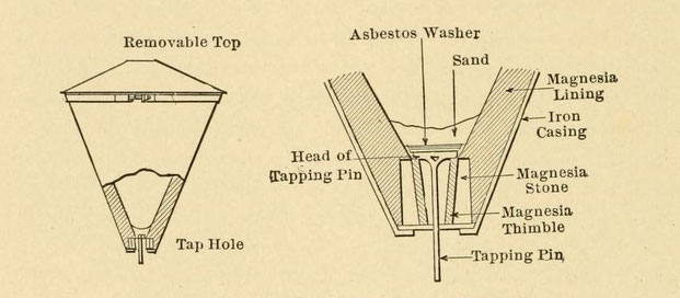
Fig. 65. — Thermit crucible with detail of lap hole.
The tap hole is the vital part of the crucible. It must remain fluid-tight until tapped, and must then withstand the rush of molten steel under pressure. As shown in figure 65, the bottom of the
crucible holds a large cylindrical magnesia stone which has been placed in position before the magnesia lining has been tamped in. Resting inside the stone is another conical-shaped magnesia
stone, called the "thimble." It is also hollow, and its core is the channel for the molten steel. An iron tapping pin, having a long shank and a flat head, is dropped into the hole in the
thimble; its head acts as a plug to the channel. An asbestos washer is dropped on the head of the tapping pin, then an iron washer, and next an inch of silica sand is poured on the iron washer.
This makes a plug to the crucible that is fluid-tight for at least a minute, long enough for the reaction to take place.
This plug is tapped by driving the pin up from the outside by hitting it with a spade. The fluid rushes out and melts the tapping pin as it goes. A new tapping pin is needed with each reaction; a
new thimble every eight or ten reactions; a new crucible lining every twenty to more reactions.
The lining of the crucible is a mixture of tar and magnesia, which is tamped in between the crucible steel and an iron matrix. When lined, the crucible is baked at a red heat for six hours, when
the lining becomes hard. Even such a substance as magnesia melts away under the heat of the thermit reaction, and after several melts the interior resembles the walls of a Bessemer
crucible.
The Mold
Molds for thermit work are adapted to the particular joint to be made. For welding a number of joints of uniform size the company furnishes patterns with which the operator can make his own
molds, or else the company will furnish the molds themselves. Thus it will be convenient and cheap to buy or make special molds for continuous rail welding, pipe welding, rod welding (as in the
case of steel rods in reinforced concrete), locomotive-frame welding, or in other repair work that turns up regularly.
Take the case of rail welding, such as the welding together of a continuous third rail for the Paris, France, subway. We will presume the mold patterns (Fig. 66) to represent the obverse shape of
the rail.
The patterns are laid down, face upward, and covered with their respective mold boxes (Fig. 67).

Fig. 66. — Rail patterns.

Fig. 67. — Rail mold boxes.
The molding material is then rammed into place, and when the box is level-full, the operator pricks a number of holes all the way through the mold to allow the escape of gases when the mold is in use. As soon as formed the molds are placed in a drying oven for six hours at a heat of 500° F (260° C), until they have become a light brown color. Do not let them burn black, as they will then crumble easily. The molds are generally cast inside of an iron retaining frame or with iron handles.

Fig. 68. — Finished rail molds.
Mold sand must be more refractory than the ordinary river sand, which has enough iron and alumina in its make-up to render it easily fusible by the hot thermit. Coarse white silica sand and fire
clay in equal proportions is the best, price considered. Cheap rye or wheat flour, proportion of 1 to 15, is the binder used.
The sand and flour are mixed dry and then moistened to a stiff mass. Where an extra strong mold is needed, the operator can mix a spoonful of turpentine to each mold portion. For binding material
it is not advisable to use the foundryman's occasional expedients, such as molasses, larger amounts of flour, clay, pitch, etc., for two reasons: The binder is subject to the great heat of the
molten thermit.
The more binder used, the greater space will be left when it burns out, and the mold will fall to pieces after two or three usings. Also, if much binder is used, its rapid burning will cause
excessive gases which may burst the mold, and which are also liable to injure the composition of the steel joint. A good sand-flour mold should last for ten or more welds. Its life depends on the
operator's skill in making and his care in using it.
For the welding of joints similar to rails, the molds used will vary in shape, but have the same composition. The operator can carve his own patterns out of wood.
An iron mold would absorb the heat too rapidly. The thermit collar would chill prematurely, and the mold itself would probably crack or melt, being cast iron. While a soft sand mold would
propably crumble. The company furnishes a hard- baked, fire-brick mold, which is strong and refractory, at the same time being a fair non-conductor (Figs. 69 and 70).
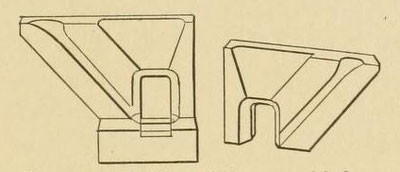
Fig. 69. — Mold partially assembled.
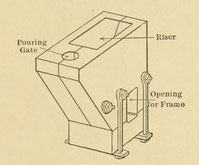
Fig. 70. — Assembled thermit mold.
For butt-welding of pipes not exceeding a diameter of 1 1/2 inches (39 mm) and of solid rods not exceeding 4 square inches (2580 mm²) crosssection, an iron mold is preferable because it is solid
and easy to handle (see Fig. 75).
For welding larger breaks, such as fractured locomotive frames, the fire-clay, or fire-brick, mold is recommended. In this case the cross-section to be welded may range from 2 by 3 to 5 by 6
inches (50 x 75 mm to 125 x 150 mm).


Fig. 72. — Tapping the crucible.
Practice
It should be borne in mind that the thermit joint itself is a steel casting of average analysis of:
Carbon
Manganese
Silicon
Sulphur
Phosphorus
Aluminum
0.05 to 0.10
0.08 to 0.10
0.09 to 0.20
0.03 to 0.04
0.04 to 0.05
0.07 to 0.18
Its average tensile strength is about 30 tons per square inch cross-section. If the joint is good, the thermit will amalgamate so closely with the metal of the welded parts that a ground and
polished section of the joint will not show any marks of junction, even though the metals be of different color and structure. Therefore, the operator has only to calculate whether he shall vary
the chemical composition of his thermit to give his weld the desired strength or whether he should gain strength by casting a big shoulder on the joint.
There are a number of instances where the shoulder must be machined off, though the weld must be as strong as the rest of the piece, as in the case of rails, bearings, etc.
Most welds permit of as large a shoulder as is needed, as in the case of ship stern-posts.
To make sure that the metal of the shoulder adheres to the parts, the latter should be made hot before the thermit is poured. If the shoulder is simply a loose collar of metal around the part, it
does not add to the strength of the weld. Where the welded part is subject to bending stresses, it is important that the shoulder be knit to the surface of the parts welded. The company
recommends heating the parts to redness if possible before pouring the thermit.
It is claimed that the air holes and shrinkage cavities, which thermit steel sometimes shows, are also due to insufficient heating (see Fig. 73). Where the parts to be welded are quite cold, it
is probable that the thermit steel freezes as soon as it touches, causing imperfect circulation around the joint, and hence allowing a faulty structure in the weld.

Fig. 73. — Reproduction of photograph of a weld showing "blow" holes.
Blow holes and separation planes are two of the common diseases of the thermit weld. Faulty mixing of the thermit "tonics," improper preheating, and improper pouring or tapping are all blamed for
these defects.
Setting the Pieces
Where two pieces of iron of more than 1-inch (25.4 mm) section are to be joined, it is best to allow a 1/2 inch (12.7 mm) space between the abutting ends, for it is necessary that the thermit
have free flow around the ends. It must either melt the abutting ends or there must be a passage between them for the thermit to flow.
In the case of rails, the ends of the rails are brought close together, as the thermit can easily melt the ends. The same is also true in the case of small rods and pipe. It is important to keep
the rails in perfect alignment while welding. In the case of locomotive frames where it is doubtful whether the thermit could melt its way into the fracture, the operator drills a line of
1/2-inch (12.7 mm) holes down the break; through these holes the thermit enters (see Fig. 85). Also in the case of anchor flukes, ship's stern- and rudder-posts, large castings, such as anvils,
hydraulic hammers and presses, etc.
In the case of locomotive frames and driving-wheel spokes the shrinkage of the joint on cooling will spoil the piece if not allowed for. The locomotive frame is jacked open from 1/8 to 1/16 inch
(3.2 to 1,6 mm) before the mold is placed. In the case of the driving-rod equal expansion of the other spokes on the piece can be had by heating short sections of each spoke to redness until the
weld around the broken spoke begins to set. All the spokes will contract together and the strain will be minimized.
Cleaning the Pieces
The thermit reaction consists in the reducing of iron oxid by aluminum. Hence it is supposed that the thermit steel, when molten, will clean the scale off the joint to be welded. So it will; but
this scale will go into solution as iron oxid. If there is much scale on the joint, the thermit joint will become full of iron oxid and will be "burnt" and brittle. Contrary to the advise
contained in the company's directions, I would recommend that the pieces be kept as clean of scale as possible. If they are heated to redness in preheating, of course fresh scale will be formed.
But the operator should begin by cleaning his pieces with sand blast or sand-paper or by tapping.
As with ordinary blacksmith welds, it is also important to rid the joint of grease by mechanical means or by scouring it with dilute alkali.
Preheating
It is necessary to heat with a torch all pieces about to be joined, for the reason that the molten thermit must meet a hot responsive surface of metal when it flows into the mold. If poured into
a cold mold and on to a cold joint, the thermit may be chilled enough to make it flow slowly and imperfectly. The result will be an imperfect junction, and the shoulder of the weld may be full of
air-holes and minute cleavage planes from rapid cooling. Do not rely on the great heat of thermit, but preheat in all cases except butt-welding.
For most work a gasoline or benzene torch is good enough. The flame is fairly neutral and will not form scale very fast.
For heating very large pieces, several torches are often needed. In shop repairing, producer gas may be used; and in this event the burner can be made to give a reducing flame, which will prevent
scale from forming. As to temperature, the joint should be at least hot enough to vaporize water drops with violence. It is well to heat the joint to redness where it can be done. But where the
pieces are large, they will conduct the heat away from the part where the flame is playing; the operator must be satisfied with a temperature ranging about 300° C.
Safe-guarding the Mold
Bear in mind that liquid thermit is exceedingly fluid — as much so as warm molasses — and as it is much heavier, it will search diligently for all openings in the mold. For this reason the mold
must be tight at the entering of the iron pieces. The operator should have at hand a bucket of luting clay, made of equal mixtures of fire-clay and sand, made pasty with a little
water.
If the molds are solid pieces, as in rail and locomotive-frame welding, he smears a thin layer over the surface of the molds where they come in contact with one another. This will make a fairly
tight mold.
Also he must stuff luting clay around the mold where the iron pieces enter, otherwise the thermit may find its way along the iron and spurt out. The danger of an unexpected squirt of thermit need
not be dwelt on. When the mold is made of fire-clay tamped over a wax collar, there should be no leaks if the operator is careful. He must be sure that his mold is rigid and strong enough to hold
the extra weight of the pour. A possible overflow of thermit and slag must be provided for. Large pours of thermit are always made with this in mind. If the pour is made in the workshop, the
floor should be of sand and the workman should remove his tools before tapping. After tapping the thermit he should remove himself as quickly as possible.
Amount of Thermit
As has been stated elsewhere, there should be twice as much thermit steel poured for a weld as is necessary to fill the space between the joined pieces and to provide for shoulder around the joint. The first of the thermit pour that reaches the inside of the joint expends most of its heat in raising the temperature above redness. It passes up the riser, leaving the interior so hot that the last of the pour settles easily around the half-molten joint and is fluid enough to make a homogeneous casting. The amount of the thermit powder used in a weld is eighteen times the unoccupied space in the mold after the joint is adjusted and ready to weld. The thermit is estimated in ounces, the space in cubic inches. This number, eighteen, provides twice as much thermit steel as is needed for the weld, the rest, as already stated, going into the riser. However, P. Redington[5] and H. L. Des Anges[6] advise that three or even four times the amount of steel is needed to get the best results. This may be due to imperfect preheating.
The Reaction
The reaction is rapid and violent. There is no explosion, but the crucible sends up a shower of sparks much like the kind of fireworks called a "flower-pot." So to prevent this and to conserve
the heat, a loose metal top is slipped over the crucible as soon as the fuse is lit.
The workman should use smoked or colored glasses to protect his eyes.
The reaction takes not longer than thirty seconds. The crucible should not be tapped for at least ten seconds thereafter, because the reaction has left an intimate mixture of slag in steel in the
crucible, and a little time is allowed for the slag to float to the surface.[7]
I believe that outside of insufficient perheating, one of the common causes of failure of thermit welds is premature tapping.[8]
No steel is strong if it is permeated with slag.
After Pouring
After pouring, you have an ordinary steel casting, with this exception — that the heat of the joint will be conducted by the body of the part much faster than is good for a steel casting. If you
are welding a fractured locomotive frame, and you want to assure yourself that the joint will be as tough as the frame, you had best give the joint several hours' annealing by such means as are
at hand.
Annealing is not so necessary in a thermit joint as it is in the oxy-acetylene and other welds. Thermit steel shows a low carbon content. Rapid cooling will not temper it highly. But no chilled
steel is as tough as the annealed product. Tests in practice seem to show that after-heating gives an even-grained and tougher joint.[9]
The results of after-heating may be attained in a lesser degree by keeping the mold in place until the joint is cooled. Cooling may take several hours with the mold on if the pieces are
large.
Nickel Addition
Nickel thermit is an allied substance to thermit proper. It is a mixture of nickel oxid and aluminum, and the reaction sets free the nickel in the metallic state.
3NiO + 2Al = 3Ni + Al2O3.
If the operator wants a higher tensile strength without diminishing his elastic limit, he introduces a can of nickel thermit into his ladle of molten iron, as already described. Or the nickel
thermit is fired in a hand-ladle, using a small quantity, and pouring in the remainder of the package gradually as the reaction progresses. The entire contents of the hand-ladle are poured into
the big ladle, which should be one-third full of molten iron. The big ladle is then poured full of iron and a can of titanium thermit is poled in to cause a thorough mixing of the iron and
nickel.
One per cent of nickel is sufficient to increase the strength of ordinary iron about one-third. Two per cent of nickel thermit gives a little more than 1 per cent metallic nickel.
Metallic nickel is also added to thermit, using 5 ounces nickel to each 100 pounds thermit if you wish to make a 1 per cent alloy.
Titanium Addition
Titanium thermit is another "aluminothermic" substance having the reaction
3TiO2 + 4Al= 2Al2O3 + 3Ti.
It is introduced into the ladle in foundry practice for the purpose of purifying the iron. About 1 per cent is recommended. As its office is to reduce the sulphur and nitrogen, most of it
reappears in the slag. Its effect is to greatly increase the strength, presumably by making the metal close-grained and homogeneous.
Butt-welding of Pipes
One of the unique applications of thermit is in the butt-welding of pipes and bars. It is a very difficult and often impossible thing to make a strong joint of two gas or water pipes without
cutting reverse threads on the two and using a sleeve union. Welding such joints by ordinary means is generally out of the question, because with the facilities ordinarily at hand, it is
difficult to obtain the right welding heat, and almost impossible to keep the surfaces clean enough to join them.
In using thermit for butt-welding, the slag of the thermit reaction is poured into the mold before the metal. It covers the iron surface in a thin layer that is at once chilled and adheres to the
metal. This coating of slag serves as a distributor of the heat of the thermit metal to the iron, at the same time preventing direct contact of the thermit metal with the pipe. As soon as the
operator believes the pipe ends are plastic, he pulls them tightly together, and the weld is effected.
As this is a very practical and necessary weld, it will be well to explain the operation and the appliances in detail. Suppose two 1-inch (ø25.4 mm) abutting gas pipes are to be welded. The ends
are first cut square and filed to smoothness, so that when the pipes touch their ends shall fit closely all around. Clamps are then fitted on the pieces, about 5 inches (125 mm) from the ends,
and screwed tightly on the pipes. These clamps have sockets for two connecting draw screws, which are fitted in place and tightened with pins (see Fig, 74) until the pipe ends touch.

Fig. 74. — Clamps in position. Pipe-welding by thermit.
Brace the pipes so that they align as they should and place the lower mold jaw under the joined ends of the pipes, so that the line of joining is in the middle of the mold. This mold is a hinged affair, having two handles, and resembles a nut-cracker (see Fig. 75).

Fig. 75. — Mold for pipe-welding with thermit.
The thermit portion, about 2 pounds (1 kg), is poured into a small cup crucible, which is lined with magnesia and operated with a pair of tongs. Allow the crucible to stand half a minute after
firing, so that the slag and steel can separate. Then pour over the lip of the crucible so that the slag comes out first. Begin pouring at one end of the lip of the mold and travel to the other
end. As the thermit slag is poured in on a cold surface of pipe, it forms a hard shell around the metal, and the liquid which follows distributes its heat evenly through this shell, which is a
poor conductor. During the pouring, the operator's assistant presses the handles of the mold together to keep the mold in close contact with the pipe. About one minute's time is allowed for the
iron of the pipe to reach welding heat. The draw pins are put in the sockets of the clamps and screwed tight. If the pipe ends are plastic and ready to weld, the operator can feel it by screwing
the draw pins. The nuts on both pins are given two full simultaneous turns by the operator and his assistant. This is enough to force the pipe ends together and complete the weld. If the operator
desires, he can force enough metal into the upset by giving the draw nuts another turn, to make the joint considerably stronger than the pipe itself.

The mold is taken off at once by tapping the upper jaw loose with a hammer. The slag collar which adheres to the pipe is knocked off carefully, and the red-hot joint is allowed to cool.
The draw bars and clamps which held the pipes together are removed as soon as the weld is cooled. The joint will have a slight upset due to the extra metal forced into it. This may be machined
off if necessary. Tests on such a weld will give a fracture or a crease in the pipe outside of the line where the mold fitted. The foregoing weld was made on a horizontal piece of piping. For an
inclined or vertical piece, the apparatus and process are the same, except that the mold will have its mouth placed in the side so that the thermit can be poured in when the mold is in place (see
Fig. 76).
For pipes or rods of different thickness or diameter, the size of the mold will vary, also the amount of thermit to use and the time it takes to raise the joint to welding heat. The manufacturers
supply both molds and clamps for pipes and rods of standard sizes, and specify the amount of thermit to use in each case.
In this application of thermit, it should be noted that the thermit steel does not come in contact with the pieces to be welded, nor does its substance form a part of the weld. Accordingly,
thermit butt-welding is applicable to pipes and rods of wrought iron and mild steel, and not to cast iron and high-carbon steel.
This process can be used for welding gas and water pipes while in the ground; steam and ammonia and compressed-air pipes; pipe coils, before or after bending; steel rods in reinforced
concrete.
The entire cost of making one weld for a pipe of 1-inch (ø25mm) bore is approximately $22. This includes the total cost of the apparatus necessary, and the time charge of one hour at thirty cents
for the operator and twenty cents for the helper. This prohibitive cost is rapidly reduced for welds in number, just as the cost of a printed page rapidly decreases as the number printed
increases. One hundred welds like the above would cost, approximately, one dollar each, supposing that two welds could be made per hour. The first cost of tongs and clamps is final, while the
crucible must be replaced after about ten firings and the mold after fifty welds. The cost of the thermit and the ignition powder and also the labor is a constant.
One of the rivals to this welded joint is the plumber's sleeve joint. In comparing the two methods of joining, the contractor must consider several things; will it be cheaper to cut a thread on
each pipe end and sleeve the joint? Also, will it be possible for the workman to get at his joint to cut the thread? Is a leak at the joint going to be a vital matter? A weld cannot leak, while
any other joint is apt to under pressure, especially where the pipes are cold, as in ammonia plants. Will a sleeve joint be strong enough in cases where the pipes are subject to strain? And,
finally, how do the total costs compare? This last will depend largely on the number of joints to be made.
Another rival is the oxy-acetylene-blowpipe weld. It is probable that with this method one workman can make from one to four welds an hour, depending on the amount of labor he must put on cutting
and fitting the pipe ends preparatory to welding. This, together with the cheapness of the gas used, makes the operating cost much less than the thermit butt-weld. However, the cost of the
apparatus, two gas storage tanks, the blowpipe, and the checks-valves is much greater. Also, to travel from pipe to pipe, often necessary, the operator would need an assistant to carry the heavy
tanks, etc.
Butt-welding of pipes can be done by the Thomson electric process. But this process is at a disadvantage here because the welding must be carried on in a heavy machine. Whereas, when pipes are to
be butt-welded, the chances are that they are in some out-of-the-way corner of a room or cellar and cannot be taken out.
Mending Defective Castings
Besides its use in welding, thermit is being exploited for the repair of defective castings, which is not strictly a welding operation. Also for raising the temperature of the ladle before
pouring for castings; for poling "burnt iron"; for the introduction of nickel, titanium, etc., into molten iron; for the formation of alloys; for the reduction of the less common metals from the
refractory ores and earths. Though these last have nothing in common with welding, they will be treated of briefly, so that the treatise on thermit may be complete.
In the foundry, in the casting of large and expensive pieces, the loss by defective castings is sometimes equal to the price asked for the casting, due to cracks, bad flows, breaks, and
inopportune blow holes. If the foundryman can save such pieces from the melting pot, he will greatly increase his profits.
For mending small surface defects, where the idea is to replace the surface without regard to the strength of the patch made, the following method is advised. First, chip out the defect to be
sure that it is superficial. Heat the casting around the hole to a red heat. Then bank a basin of sand around the hole. Place a piece of abestos in the bottom of the basin, large enough to cover
the hole. Pour thermit powder into the basin, using 18 ounces of thermit for every cubic inch (31 g/cm³) estimated space of hole in the metal. If the casting is a large one, use a greater
percentage of thermit, as more heat will be needed. Fire the thermit, and it will quickly melt the asbestos bottom, and the molten steel will be deposited in the hole in the metal. When cool, the
protruding metal is machined off.
This reaction is too rapid for the complete separation of the slag, some of which may be lodged on the junction of the thermit metal and the casting. Also, it is likely that the local heating
will cause weakening stresses in the patch when it cools; while it may also be full of blow holes if it cools rapidly, because of conduction. It is claimed[9]
that the shrinkage is so great that such a repair is unsafe and useless.
Thermit may be used for repairing fractures in castings before they leave the foundry. If the casting have a piece broken cleanly off, this may be joined at a less cost than the cost of
recasting. Also cracks may be drilled out and thermit used.
Thermit in Foundry Practice
Thermit may be introduced into the ladle before pouring for a casting. If the piece to be cast is long and thin, or if it has intricate parts which require a very hot metal to produce, the temperature of the iron in the ladle can be raised by plunging a can of thermit into it and holding it at the bottom until both thermit and can have burned up and the slag has come to the surface. The excess heat of the thermit will raise the temperature of the ladle (Fig. 77).
How much thermit to use for a given amount tail of thermit of iron cannot be stated definitely — probably 5 per cent. It depends on the initial temperature of the ladle, the demand of the casting, and the cost. The cost prohibits its use except for special work, such as the casting of stern-posts for ships, and the production of small castings which can be made at any time without the capital investment for a special converter plant.
The company also recommends placing a can of thermit in the riser of such a casting as a ship's stern-post. If the post is to be a long one, "the metal cools very rapidly during its passage through the mold, and becomes so sluggish that the pressure of the runner is not sufficient to force the metal up the rising heads more than one-half of their length." The thermit can reinforce the heat of the rising metal.
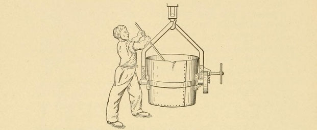
Fig. 77. — Thermit can be plunged into ladle.

To prevent "piping" of steel ingots, a can of thermit may be plunged into the ingot. The operator waits until the ingot has begun to solidify. The "pipe" will then begin to form, due to the chilling of the steel on the outside and its contraction. Break through the top crust, and thrust the can well down into the ingot. It will ignite and raise the temperature of the upper part of the ingot to remelting. A solid ingot will result (Figs. 79 to 81). This is another use for thermit, questionable, because of its cost.

Fig. 79.
— Steel ingot showing defective head piping without anti-piping thermit.
Fig. 80.
— Showing ingot with box of anti-piping thermit in position.
Fig. 81.
— Ten-ton steel ingot having been treated with anti-piping thermit.
Poling
As has been described, the foundryman often freshens his "burnt iron," by stirring the ladle with a green stick of wood. "Burnt iron" contains oxygen in the form Fe2O3. This oxid of iron impairs the strength of the iron very much. By stirring the molten mass with a green limb, the workman has added carbon which reduces the iron oxid, as follows:
2Fe2O3
+ 3C = 4Fe + 3CO2
The limb being full of water also throws out steam which causes the iron to boil. This makes the reaction complete throughout the mass. When the oxid is all reduced, the ladle is "fresh." But
this operation, called "poling," lowers the temperature.
Now "poling" can be done with a thermit can on the end of a rod instead of with a green limb. The composition of the thermit must be varied so as to have a positive effect on the oxid of iron;
that is, there must be a slight excess of aluminum. Thermit "poling" has the advantage that it raises the temperature of the molten iron. But it should not be used except in ladles of steel,
because at the heat of molten steel there is complete reaction with the excess aluminum in the thermit.
While at the lower temperature of molten cast iron, the reaction would be confined to the thermit can. The excess of aluminum would not react on the iron oxid of the burnt mass, and both would
stay in solution. In other words, the iron would be poorer than ever.
A better method recommended by the company is the use of manganese with the thermit, though no doubt the thermit can be omitted if we do not wish to raise the temperature. Pure manganese, made
"thermochemically," can be used. Manganese, in the form of ferro-manganese and spiegel, have long been known to furnace men as a cure for "burnt iron" and a toughener of their product. W. M.
Carr[10]
is authority for the statement that a large ladle can be used for a small converter if thermit be added to the first pour in the ladle immediately preceeding the second pour. The ladle held 5
tons, the converter 2 tons, the pours were forty-five minutes apart. The thermit was poled into the first pour, as usual, in a can on a rod. It freshened the iron and raised its temperature to
about that of the second pour.
Adaptability
In summing up the thermit process as a whole it will appear that it is especially suited for welding and repairing large pieces. In pieces ranging below 4 square inches (2580 mm²) crosssection,
it has to meet competition with the oxy-acetylene, oxy-gas, oxy-hydrogen, electric, and smithing processes. Its application to butt-welding is very often the cheapest, handiest, and most
workmanlike.
In rail welding it has to compete with the electric process, which was the pioneer in this field. In welding motor cases for steel cars it has to compete with the oxy-actylene process.
In welding fractured locomotive frames it is used with success, and is evidently as cheap as can be had — certainly, much cheaper than the old blacksmithing, for the weld may be effected often without dismantling. It is used in their repair shops by many of the railroads in this country and abroad for repairing engine frames and also driving rods and spokes, and occasionally the repair machinery. The Central Railroad of New Jersey first introduced thermit in their shops.

Fig. 82. — Fracture on locomotive frame, opened up by drilling and held in place by jacks in preparation for thermit welding
It is used for occasional repairs of fractured gun-carriages and parts. Also for crank shafts, embossing dies, shears, and anvils, in cases where it is cheaper to repair than to replace.
For broken rudder and propeller shafts, skegs, and stern-posts of vessels it is invaluable. This is the most notable feature of the process. Before the advent of thermit, a break in one of the
parts named meant the dry-docking of the vessel for weeks, the displacing of the part broken and its repairing at great expense and trouble, or sometimes its displacement. Besides the actual
expense entailed, much was lost by having the boat out of commission.
Since the use of thermit for such repairs, dry-docking is still necessary, but the whole operation can be gone through with in much less than a week; the vessel is not dismembered and the weld
may be made the strongest part of the piece. Broken anchors can be mended in a few hours. As already described, there are many instances of such quick, cheap, and strong welds.
Thermit is almost a new subject. It has been known to the repair men since about 1904. It is already a definite success, and under the energetic experimentation of the Goldschmidt Co. it is
likely to prove useful in ways at present unthought of. It is likely that special thermits will soon be invented for welding other metals than iron and steel.
Typical Welds
In the welding of rail joints in quantity there are a number of large contracts that have come to notice. Among them the joining of the third rail of the Paris subway; the welding of 10,000
joints of the Electric Traction Company of Adelaide, Australia; the welding of the Lexington Avenue line in New York City. The latter was especially difficult because of the heavy traffic. It was
impossible to do the job by daylight without tying up the traffic. In the early morning hours, when the cars run on a ten-minute schedule, the company succeeded in carrying on their welding with
only the occasional holding up of a car.
The cost of thermit rail welding has been variously estimated. Track at Holyoke,[12]
Mass., welded in 1904, cost $6.23 per joint. The longest unit rail made was 2300 feet. In the same year rail welding at Hartford,[13]
Conn., cost $5.00 per joint, which figure includes repaving.
Among pipe-welding contracts, that carried out for the Manhattan Refrigerating Co.,[14]
of New York City, is noteworthy. Their entire system of piping was welded by the thermit process. There were twenty-nine 1 1/4-inch (ø31.8 mm) joints, and twenty-seven 2-inch (50.8 mm) joints,
both under a cold pressure of 180 pounds (12 bar). The result is reported as successful. This is a decided improvement on the sleeve joint for ammonia systems, because the contraction of the
pipes due to the extreme cold is certain to allow leakage in the sleeve joint.
Repair of the 'Betsy Ann'
“One of the quickest repairs on record was accomplished on the Mississippi River Steamship 'Betsy Ann,' belonging to Learned & Son, Natchez, Miss. This is a stern wheel boat, the shaft being
a hexagonal one, 8 3/5 inches (ø218 mm) on the inscribed circle and over 23 feet (7 m ) long.”[14]
“A crack developed on one of the faces and ran down a short way on the second face, the total length visible being about 4 inches (100 mm). Attention was first called to this by rust showing
through the paint and after examining the shaft carefully it was decided to run the steamer to see if the crack extended. Within a short time it was noticed that the crack had extended 3/4 inch
(19 mm) since the first observation, and it was therefore decided that a repair of some sort should be made on it at once. Preparations were made to weld a collar of Thermit steel around the
shaft at the fracture and thus to restore it to its original state of usefulness. A pneumatic chipping hammer was used for cutting away the metal to the bottom of the flaw, so that the
superheated Thermit steel could be led to the deepest part. After this had been accomplished, the paint was cleaned off a distance of 5 inches (127 mm) on either side of the fracture and the weld
effected by the wax pattern method, as previously described; 416 pounds (208 kg) of Thermit, 35 pounds (17,5 kg) of mild steel punchings, and 8 pounds (4 kg) of metallic manganese being required.
After allowing five hours for the metal to set, the mold box was removed and the weld found to be so satisfactory that the steamer immediately proceeded on her trip without waiting for the gate
and riser to be cut off; in fact, the repair was accomplished without causing the steamer to miss a single trip” (See Fig. 62).

Fig. 83. — Finished thermit weld of S. S. 'Betsy Ann' before removing metal left in gate and riser.
Repair on Steamship 'Corunna'
“This was a vessel of 1296 tons register, 240 feet long, 35 feet beam and 21 feet depth (73 m long, 10 m beam and 6,4 m depth). In getting away from her pier in the Lachine Canal, Montreal, the stern of the vessel was caught by the current and swung against the stone walls of the canal, the shoe or skeg being broken off close to the keel, while the rudder-post was broken at a point about 10 inches (254 mm) from the top of the rudder. Owing to the serious nature of the injuries it ordinarily would have been necessary to tow the vessel to Cleveland (there being no adequate dry-dock in Montreal to make these repairs in the usual way).”
“It was soon decided that, without doubt, several thousand dollars could be saved by repairing the frame and rudder-post with Thermit.”
“On inspection it was found that the rudder-post was broken off inside of the tube, while the stern frame had been bent 12 inches (304 mm) out of line, the shoe being completely broken about 13
inches (330 mm) from the central line of the post. On account of the break in the rudder-post being by an old scarf weld, fully 11 inches (280 mm) inches in length, it was not deemed advisable to
attempt to weld this again, so about 14 inches (355 mm) of the rudder-post adhering to the rudder was cut off and a new piece of shafting, 8 feet (2,4 m) long, welded on in place of the old post,
as shown in the illustration. In order to facilitate the operation, the rudder was removed from the ship and the post welded on shore, this being done to prevent interference with the operation
of welding the stern frame.”

Fig. 84. — Finished weld on rudder post of steamship 'Corunna.'
“It being necessary to have a supply of compressed air in order to operate the gasolene torch and pneumatic tools, an old Westinghouse steam-driven air-brake compressor was obtained and mounted
on board ship, the steam being piped from a donkey boiler. A receiving tank was placed on the edge of the boiler and piped to the compressor. With the apparatus in place, preparations were made
to effect the welds in the usual way, the rudder-post weld being reinforced by a collar 3 inches (76.2 mm) long and 1 inch (25.4 mm) thick, while the stern-post was reinforced with a collar 8
inches (203 mm) long, 1 inch (25.4 mm) thick at the top and sides, and 3/4 inch (19 mm) thick at the bottom; the latter being done in order that the draught of the vessel might not be made any
greater than could be helped. One hundred and fifty pounds (75 kg) of thermit, 25 pounds (12.5 kg) of steel punchings, and 3 pounds (1.5 kg) of metallic manganese were used in welding the
rudder-post, while 350 pounds (175 kg) of thermit, 70 pounds (35 kg) of 1 by 3/8 inch (25.4 by 9.5 mm) steel rivets and 7 pounds (3.5 kg) of metallic manganese were required for welding the stern
frame.”

Fig. 85. — Thermit weld on stem post of steamship 'Sochem.'
“While the total time required for the operation amounted to five working days, there is little doubt that had the work been done in a properly equipped dry-dock, it could have been accomplished
in three days or less.”
Weld of Electric Motor Shaft
“It has usually been deemed necessary to leave a reinforcement or collar of thermit steel around the various welds made by the thermit process. An instance has occurred recently, however, where
this reinforcement was machined off and the weld subjected to very severe strains, but without causing any weakness to show up.”
“The case in question is that of an armature shaft 3 inches (76.2 mm) in diameter, 14 1/2 inches (368 mm) long, and required to transmit 50 h.p. to the main hoist of a 50-ton Shaw electric
crane.”
“The weld was made in the shops of the Central Railroad of New Jersey, Elizabethport, N. J., and the armature has now been in service since October 8 (probably 1909) and is giving perfect
satisfaction in spite of the fact that all the surplus metal about the weld was machined off and the shaft turned down to its original diameter.”
“The weld was made 9 inches from the hub, and is shown in the accompanying illustrations" (Fig. 86).”

Fig 86. — Weld made at shops of the central railroad of New Jersey on a motor armature shaft.
Chemistry and Thermics
The chemical formula for the present thermit reaction is
8Al + 3Fe3O4
= 9Fe + 4Al2O3
Expressed in weights, it is 217 parts aluminum + 732 parts magnetite = 540 parts metallic iron + 409 parts slag, or, approximately, 3 parts of aluminum and 10 parts magnetite will produce, on
combustion, 7 parts metallic iron.
Commerical thermit is a mixture of finely granular aluminum with less finely granular magnetic iron scale. The aluminum is about the fineness of granulated sugar; the scale is like coarse sand.
The ratio by weights is three of iron scale to one of aluminum. Dr. Goldschmidt began his experiments with similar mixtures about 1895. Thermit was not heard of before 1902. He speaks with
feeling of the mechanical and chemical difficulties that hindered the perfection of his ideas. So there is good reason to suppose that the thermit mixture is about the best that can be made, both
in its physical form and in its reaction. The difficulties that confronted Dr. Goldschmidt were:
1. The violence of the reaction.
2. How to get a good homogeneous steel out of the reaction.
One of the troubles with thermit reactions is their violence. The burning of several metals, as calcium, is so brisk that the contents of the crucible boil over and metal and slag alike are lost. Probably for this reason the magnetic oxid was substituted for the hematite oxid. Early literature gave the reaction as
2Al + Fe2O3
= Al2O3
+ 2Fe
but Dr. Goldschmidt[16]
gives the present reaction as between aluminum and magnetite, and a casual examination of thermit by means of a magnet shows that magnetite is now used. It is likely that the magnetic oxid gives
a slower burning than does the sesquioxid. The magnetic oxid is made of granulated rolling-mill scale.
The aluminum is powdered by a secret process. At present there are two known ways of pulverizing metallic aluminum. The first is to raise the metal to an approximate 600° C, at which heat the
metal becomes brittle and granular, and can be ground between rolls. The second way is to blow air through red-hot aluminum so as to partly oxidize the metal. It is then cooled to about 600° C,
and ground, the oxid of aluminum helping to separate the metal into fine granules.
As will be guessed, a small amount of thermit will burn more slowly than a large amount. The heat of a large burning, such as for repairing a propeller shaft or large engine fly-wheel, will be so
intense that the crucible will boil and throw out part of its contents. To prevent this, from 5 to 15 per cent, by weight of thermit, of cold steel billets and turnings are added to the thermit
before burning. This iron takes up the excess heat. Of course this added steel must be of correct chemical composition.
While it is important to keep down the boiling reaction, it is even more necessary to get a resultant steel that will be strong, elastic, and dense. The quality of the thermit steel will depend
on its chemical composition. Good steel is low in sulphur, phosphorus, and silicon, and not too high in carbon. The following “Average Composition of Thermit Steel” is given by the Company:
Carbon
Manganese
Silicon
Sulphur
Phosphorus
Aluminum
0.05 to 0.10
0.08 to 0.10
0.09 to 0.20
0.03 to 0.04
0.04 to 0.05
0.07 to 0.18
Of course, to produce a steel of the above composition, the aluminum and iron scale that make up the thermit must be very pure. It would be a problem to obtain sesquioxid of iron of sufficient
purity and at the same time as cheap as rolling-mill scale. Sesquioxid or hematite ore always contains one or the other of the impurities in considerable extent and is of variable composition;
while, in using scale from Bessemer or open-hearth steel the impurities would be already known and would be much lower.
In regard to the proportioning of the mixture, the formula calls for 3 parts of aluminum to 10 of iron oxid; the thermit mixture is 1 of aluminum to 3 of the oxid.
In nickel thermit the reaction is
2Al + 3NiO = Al2O3
+ 3Ni.
By weight, it is 54 parts aluminum and 224 parts nickel oxid give 176 parts metallic nickel. Or, approximately, 1 part aluminum and 4 parts nickel oxid give 3 parts metallic nickel. Nickel
thermit, however, contains 5 parts of nickel oxid by weight to 5 of aluminum.
Besides the aluminum-iron oxid reaction, a number of others have been and are being tried. It is possible that the future thermit may dispense with aluminum and substitute another metal for
reducer. “Weldite,” an English product, uses silicon and aluminum with Fe2O3.
Dr. Goldschmidt himself has tried other combinations: for instance, aluminum and calcium, which, according to Dr. Richards,[17]
or [18] give a greater heat due to the formation of calcium-aluminum slag. He gives the probable formula
5Fe2O3
+ 3CaAl2
= 3(FeO.CaO.Al2O3)
+ 7Fe
and claims that 70 per cent of the iron would be reduced from its oxide; and that one part calcium-aluminum alloy will produce one and four-tenths of liquid iron (metallic).
Calcium[17]
alone can be used to replace aluminum, but the reaction is so violent that sometimes the contents fly out of the crucible. The addition of 30 to 40 per cent fluor-spar (CaF) or 10 to 20 per cent,
quicklime (CaO) gives a saner reaction.
Heat of Reaction
Richards[18]
has calculated the heat of the thermit reaction as 2694° C. The temperature commonly given by the manufacturers is 3000° C. M. Fery, using his new radiation pyrometer, found the temperature of
the stream of steel as it flowed from the crucible to be 2300° C — probably about right when one makes allowance for the chilling effect of the crucible. Taking the melting point of steel as
roughly 1350° C, the thermit steel is nearly twice as hot.
Testing
The strength of an ordinary weld in wrought iron varies from 10 to almost 100 per cent, of the strength of an equivalent cross-section of the metal. In general, however, a weld made under proper
conditions runs between 50 and 70 per cent, for high-carbon iron and between 60 and 80 per cent, for low-carbon iron. The strength of a thermit-weld is subject to quite as great variance, for the
reason that thermit steel is a definite compound and may be -of quite different composition from the parts welded by it. Also it is well to bear in mind that the initial strength of thermit steel
itself is subject to variations due to the amount of included slag, air holes, and to the rapidity of cooling; also, the chemical composition can be varied by the addition of alloy formers, such
as nickel, chromium, and manganese; and the addition of titanium and manganese in small quantities, which are purifiers.
A number of tests of different character have been made by the company and by railroad and repair shops, some of the results of which are given as follows:
Test No. 1:[19]
“At the St. Louis and San Francisco Railroad shops, Springfield, Mo., recently the following test of a thermit-weld was made:”
“A section of a cast-steel frame, 4 by 5 1/2 inches (102 by 140 mm), was welded by the thermit process. In making the weld 75 pounds (37.5 kg) of thermit, 12 pounds (6 kg) of punchings, and 1 1/2
pounds (750 g) of manganese were used. For molds, fire-brick was used, cut to shape.”
“After the weld was cold, the collar on the bottom and one side was planed off 1/4 of an inch (6.4 mm) below the original surface of the casting, in order to show the place where the two metals
had joined. The riser also was cut off, leaving the collar, however. The weld was absolutely solid, not a single blow hole appearing anywhere — not even the riser.”
“The welded section, now 3 3/4 x 5 1/4 inches (95 x 133 mm), with collar 1 inch (25.4 mm) thick on top and on one side, was then placed in wheel press on supports 14 3/4 inches (375 mm) apart and
a piece of hardened steel, 1 inch square (645 mm²), placed as shown in figure 87.

Fig. 87. — Arrangement of test piece for test No. 1.
“A pressure of 170 tons was applied before breaking. The fracture started at the bottom outside welded section, extending into the center of the weld at the top. The fracture showed that perfect
amalgamation of the metals had taken place.”
“In comparing the strength of this weld with original stock, assuming a maximum stress in the outer fiber for cast steel of 60,000 pounds to the square inch (414 N/mm²), a section 3 3/4 x 5 1/4
inches (95 x 133 mm) tested in the same way would break at 100 tons.”
In this test No. 1 it is presumed that the 12 pounds (6 kg) of punchings were mild steel. The manganese was used to freshen the iron, and most of it probably slagged as manganese oxid and came to
the surface.
Test No. 2:[20]
“Two test bars taken from the upper part of a previously, but unsuccessfully, poured casting gave, on an average, 66,000 pounds per square inch (455 N/mm²) tensile strength and 9.5 per cent,
elongation on a measured length of 2 inches (50.8mm). This casting showed in all the sections a clean, non-porous, dense grain. It appears possible, therefore, to produce steel castings of
thermit and, in a case of necessity, the higher price would not be of importance.”
Test No. 3.[21]
The thermit process has been used by the Fore Shipbuilding Co. of Quincy, Mass., who have made a number of tests of the physical properties of thermit metal. Bars of rolled steel, of section 2 x
4 1/2 inches (50.8 x 114.3 mm) were drilled, broken, and welded with thermit. Standard test bar were cut from the centre of the welded bar, and were submitted to the ordinary tests. As the test
pieces were of uniform size, both in the stock and the welded section, the result is worth recording:

It is to be noticed that the tensile strength is 12.7 per cent less in the weld than in the stock, and the tensile strength 2.5 per cent less — a fair showing.
Test No. 4
— By the Illinois Steel Co., Chicago.[22]

Test No. 5 — By the Pennsylvania Railroad, Altoona, Pa.[22]

Test No. 6:
It has been suggested that the thermit-weld may be strong in itself, but that it weakens the adjacent iron. To find if this is so, a section of welded rail was subjected to equal blows by a steam
hammer, both on the unaffected rail and on the metal nearest the weld. The die used was a blunt tool, 1/4 inch (6.35 mm) in diameter. Measurement with a micrometer showed a depression of 0.1432
inch (3.6373 mm) in the rail nearest the weld and 0.1596 inch (4.0538 mm) 3 feet (914 mm) from the weld.
Tests, under varying conditions without number, might be multiplied. But for the practical man, those already given show that the ultimate strength of the thermit steel in practice can be
estimated as over 30 tons to the inch section. By practice, I mean the thermit steel produced for repair work, according to directions: thermit, about 5 per cent[23]
mild steel punching, and about 2 per cent[24]
manganese for purifier.
Annealing for 3 hours brings the elongation well over 10 per cent.
Addition of about 3 per cent[24]
nickel raises the ultimate strength about 5 tons without decreasing the elastic limit. Further addition of about 2 per cent[24]
of chromium with the nickel brought the elastic limit to about 47 tons — as high as can be wished. Addition of 1 per cent titanium raises the tensile strength. Tests have also been made of
thermit steel that has been toned up with molybdenum, ferro-silicon, etc.
Remarks and References
- Richard N. Hart: The Thermit Process. In: Welding Theory, Practice, Apparatus and Tests. Electric, Thermit and Hot-Flame Processes. McGraw-Hill Book Company, London, 1910, p. 121-158.
- Fig. 62 is numbered Fig. 83 in the original publication.
- Transactions of the Iron and Steel Institute, 1869; On a New Process for Removing Silicon from Pig Iron.
- Fig. 63 is shown upside-down in the original publication.
- Foundry, April, 1905.
- Foundry, August, 1905.
- Foundry, R. Webb, July, 1905.
- Foundry, Jas. F. Weber, July, 1905.
- Journal U.S. Artillery, Gustav Reiniger, July-August, 1907.
- Mending a Casting with Thermit, Pat Redington, Foundry, April, 1905.
- Development of the Thermit Process in Foundry Practice, Foundry, July, 1906.
- Street Railway Journal, Feb. 18, 1905.
- Street Railway Journal, Jan. 28, 1905.
- Iron Age, Nov. 16, 1905.
- Reactions, published by Goldschmidt Thermit Co.
- Electrochemical and Metallurgical Industry, Sept., 1908
- Engineering and Mining Journal, June 15, 1907.
- Electrochemical and Metallurgical Industry, J. W. Richards, June, 1905.
- Reactions, Vol. I, 1908, published by Goldschmidt Thermit Co.
- Iron Age, April 26, 1906.
- Journal United States Artillery, Gustav Reiniger, July-August, 1907.
- Transactions of the Society for Testing Materials, E. Stutz, 1905.
- Calculated from weight of thermit powder.
- Calculated from weight of test bar.