


Aluminothermic Rail Welding
Aluminothermic rail welding (also known as thermit welding or thermite welding) was invented in 1894 by Hans Goldschmidt in
Germany and became popular in the U.S.A. during the electrification of street railways to reduce the electrical resistance of the rail joints. The inventor presented a paper on
'Alumino-Thermics and Rail Welding' to
the Columbia University Chemical Society on 13 November 1903. Subsequently, George Pellissier
was
the first American to use the process
commercially for laying one mile of track of the Holyoke Street Railway in Massachusetts in August 1904.
The abstract of Hans Goldschmidt's paper is reproduced below:
Alumino-Thermics and Rail Welding
By Dr. Hans Goldschmidt
Abstract of lecture before the Columbia University Chemical Society, 13 Nov. 1903[1]
The large field of welding processes with the aid of thermit — which is at present the most important application of alumino-thermics — has been considerably broadened in recent years. The most important of these welding processes is the one by which a continuous rail — a necessity of modern trolley road construction — is simply, cheaply and effectively obtained. Engineers in this country (i.e. U.S.A.), in which no less than 25,000 miles (40.000 km) of single track are in existence, are watching the good results obtained in Europe with this system.
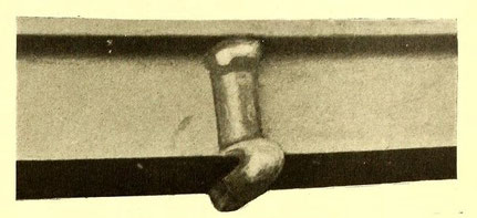
Side of rail, showing weld
The city of Leeds, in England, after careful investigation by a commission of experts, is using this process over the whole of its track, and an American expert, who had occasion to see it
employed there, recommended it for a very important contract at Singapore, where, in consequence, it is now being used over a track of 27 miles (43,5 km). Last year (i.e. in 1902) 3000 joints
were welded, and this year (i.e. in 1903) no less than 20,000 joints have been delivered. A marked advantage enjoyed by this system is the absence of any bulky equipment. All that is required is
a crucible, a mould box, and, in some instances, where a complete butt-weld of the head of the rail is desired, a rail clamp. All these materials, including the necessary quantity of thermit, can
easily be moved on a hand truck. Each weld, according to section, requires from 15 lbs. to 20 lbs. (7,5 to 10 kg) of thermit. Even where a rail clamp is used the time employed is less than that
necessary for fixing fish-plates and copper bonds.
Conical crucibles lined with magnesia
The mould is made according to a model designed especially for each section. Its two parts, one on each side, firmly enclose and exactly fit the rail. Certain channels are provided in the mould
parts for the thermit iron to run through. The size of these channels, which are open towards the rail, has been accurately determined by experiments. It varies according to whether slag or iron
is to fill the mould and also in accordance with the requirements of each section. The thermit iron running out of the crucible flows round the web and foot of the rail, and, melting them, forms
one mass with them. The liquid slag which follows the metal is diverted to the top of the rail and brings the latter to welding heat. The whole section is thus heated equally and the rail ends
will not buckle.
Mould ready for casting
The weld can be made with or without rail clamps. In the former case the rail ends are butted together by tightening the screw two minutes or three minutes after the run. A slight and very short
upset will be produced at the joint, which can easily be removed. The simplest way has been found to chisel it off, as a grinder will not answer the purpose as well. One man can take care of
twenty-five joints a day in this manner.
Complete outfit
By using the rail clamps a perfect butt-weld, without even the smallest gap between the ends, is obtained. The rigidity of the joint is particularly great, and when tested under hydraulic
pressure the break occurs outside the welded zone, for with the iron shoe welded onto the section the joint is really stronger than the rail.
The use of the rail clamps is, however, by no means obligatory. Without them the work is still further simplified, as the time necessary for adjusting the heavy clamps and for chiselling off the
up-set is saved. By practical experience it has been found that the weld without clamps is quite sufficient. Of late the clamps are being used less and less.
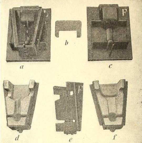
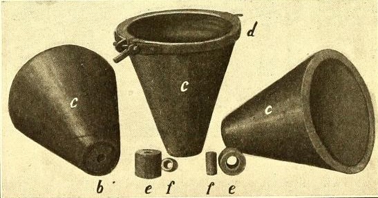
Forms and moulds:
a Model for the lip side with mould shell,
b Appliance used when ramming the sand in,
c Model for tread side,
d Finished half of mould for lip side,
e Half of mould shell for tread side,
f Finished half of mould for tread side.
The first to weld without clamps was the town of Brunswick, Germany, more than two years ago (i.e. 1901); it has continued to follow this plan ever since. Nearly all the work done in France, such
as at Rouen, Havre and Paris was without clamps, and the joints have now been in the ground for more than a year. Italy also, particularly the cities of Genoa and Milan, preferred to work without
clamps.
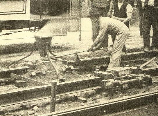
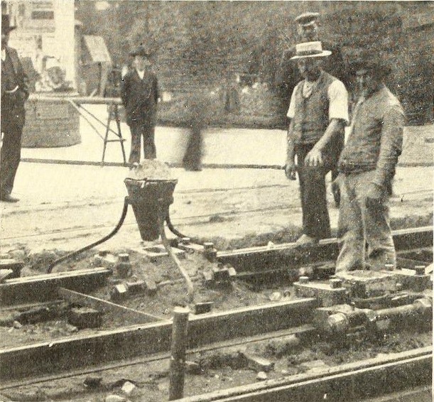
Welding track at Dresden
Altogether this modification has been tried in several thousand joints and given entire satisfaction. The use of clamps is based chiefly on theoretical considerations. Even a butt weld can be
obtained without clamps, particularly with rails already embedded. At Barmen, Germany, this was done very successfully about a year and a half ago (i.e. mid 1902). The old fish-plates were taken
off, the ends of the rails were raised slightly by means of a crowbar, and a shim was firmly wedged in between; in this case the shim is welded into the head of the rail.
When welding new rails not yet embedded the use of rail clamps can be obviated by firmly wedging up the rail from the next succeeding joint. When working without clamps the time consumed per joint equals three-quarters of an hour for one man; trained squads of four men, including foremen, did not use nearly so much time. At $1.50 per day the wages item of cost is 10 cents per joint. The use of the clamps doubles this amount. All other labor connected with welding remains the same whether clamps are used or not.
As stated the moulds are in two parts. They can either be made on a large scale by manufacturers of refractory earthen-ware, or, according to the requirements of the trolley lines, in the repair shops. In the latter case they are made by ramming a simple mixture of sand and loam into a sheet-iron case, which afterward has to be dried during a couple of hours at a temperature of some 100 C. The cost is, therefore, only a few cents.
The mould is dry and porous, and is screwed onto the rail, and the rims are carefully smeared with clay where they touch the rail. Prior to this, however, the rail ends are cleaned of dirt and rust with a wire brush, and are slightly warmed. A sand blast is superfluous.
In case the tops of the rails are to be butt-welded the section has to be filed. This is all that is required in the way of preparatory work. A true alignment of the rail is, of course, an indispensable precaution. The rails require no bolt holes, as no provisional fish-plates are necessary. In wet weather the protection of a few planks is desirable to prevent the mould and thermit getting wet. None of this work demands special training, and can easily be done by inexperienced labor.
The next and only appliance remaining necessary for thermit welding is the crucible. This consists of a sheet-iron mantle lined with magnesia. It is of simple construction, the lining being introduced by ramming it round a cone which is suspended in the middle of the mantle. The bottom is formed by a hard magnesia stone provided with an exchangeable outlet, which will stand from nine runs to 10 runs. The crucible, with the cone in it, is placed in a furnace for two hours until it is brought to a glow heat, when it is ready for use. Crucibles will stand about twenty-five reactions, and the wear and tear will, therefore, amount to only a few cents per joint. Every section, according to its weight and according to its different dimensions, requires different quantities of thermit, the composition of which has also to be regulated for each separate case.
Although sections generally in use in this country are higher than the average European standard, the less width counterbalances in a certain degree the increased height, and the quantity of thermit required will average about the same in both countries.
Thermit is supplied in small bags, containing the exact weight which is needed to effect the weld. These are called welding portions. The trolley companies may make their own crucibles and moulds, and they will, therefore, have to pay freight only on the welding portions. As these weigh about 20 lbs. (10 kg) gross the freight is, of course, considerably less than that on fish plates and bolts. The Essen Works have a plant to supply over 500 welding portions daily. The illustrations which accompany this article show clearly the methods and apparatus employed, both in track welding and for contact rails.
The strength of the weld is about 80 per cent of the strength of the original material. The shoe welded onto the foot of the rail not only makes up for the remaining 20 per cent but materially strengthens the rail at the joint. The head does not get softer although it is brought to welding heat, the reason being that the operation takes place without the air having access to it. Test rods, cut out of rails, brought to welding heat with thermit, have proved this contention. Tensile strength and elasticity have not suffered. Three years practical experience in over forty towns in Europe confirms these conclusions.
Table of Tests
- Up to 28 tons, no deflection and no set, and then 1/64 in (0,4 mm)
- Up to 30 tons, 1/32 in. (0.8 mm)
- Up to 40 tons, 1/32 in. (0.8 mm)
- Up to 45 tons, 3/64 in. (1.2 mm)[2]
- Up to 50 tons, 3/32 in. (2.4 mm)
- Up to 55 tons, 3/32 in. (2.4 mm)
- Up to 60 tons, 1/8 in. (3.2 mm)
- Eighty-five tons. 3/16 in. (4.8 mm) set.
- Ninety tons, 1/4 in. (6.4 mm) set.
- Ninety-five tons, 1/2 in.(12.7 mm) and slight fracture.
Thermit welded joint tested to dead load as above:
- Up to 60 tons no permanent deflection.
- Safe dead load at 68 tons.
- Seventy tons fractured at side of the weld, the welded portion remaining intact.
- Permanent set at 85 tons, 3/4 in. (19 mm)
- Permanent set at 90 tons, 7/8 in. (22,2 mm)
- Fractured at 102 tons
The so-called third rail is also welded by this means. The skin resistance of copper bonds increases with time, and frequent repairs are necessitated thereby, but welding obviates these repairs.
It can be done in two ways. The first is identical with the one described before (but without the use of clamps), and is now in operation on 20 miles (32 km) of road at Paris, France, where a
short track gave satisfaction after a year's trial. The second consists in welding a small bridge of thermit iron between the feet on one side of the rail. Both are in use on a large scale.
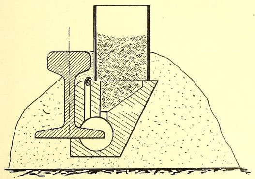
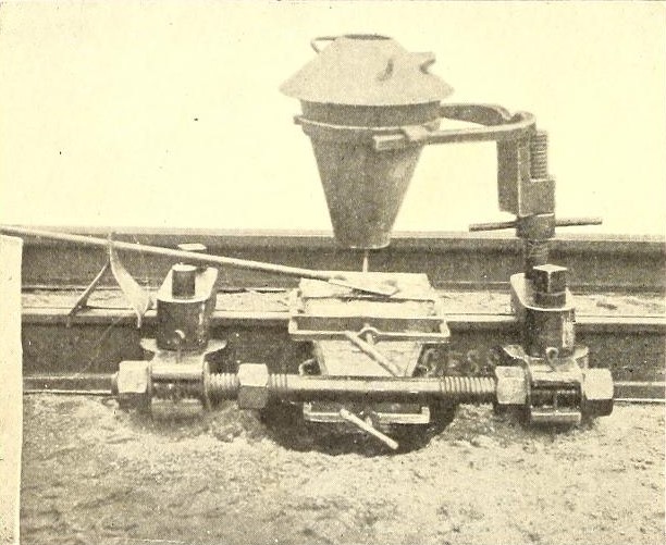
Welding third rail
On the Suburban Road from Berlin to Grosslichterfelde, the Union Elektricitäts-Gesellschaft of Berlin has welded 13 ½ miles of track. In this case the crucible is superfluous. The welding
portion, of about 3 lbs. (1.5 kg), is placed directly into the upper part of the mold, which is prolonged by a piece of gas pipe. The accompanying cut shows the third rail and the mould at the
right hand. A tube is placed above the mould and filled with thermit iron. At the bottom the thermit iron mixture rests on a thin iron plate. When the thermit mixture is ignited this plate melts,
and the molten mass flows into the mould and the weld is made. The ignition is made by placing about a thimbleful of ignition power in the crucible and setting fire to it with an ordinary
match.
References
- Street Railway Journal. 14 November 1903, p. 887-889.
- Erratum: Due to type-setting errors in the original publication this line should probably be spelled as "Up to 45 tons, 3/64 in (1.2 mm)" instead of "Up to 45 tons, 1-64 in".