


Aluminothermic Welding of Railway Tracks
The article describes the process of Thermit welding (also known as thermite welding) using 39 photos taken by Christina Nöbauer on 14 October 2016 during construction work on the Pinzgauer Lokalbahn in Zell am See. This is a narrow-gauge railway with a gauge of 760 mm (Bosnian gauge) in the Austrian province of Salzburg.
The entire sequence lasted about half an hour, which is documented in the time stamps shown in the captions. The high-resolution photos can be enlarged by clicking on them.
Process Sequence for Thermit Welding
The rails are already laid. The rail ends are cut with a flame cutter so that a 20 mm wide gap remains between the rail ends.

10:11:12 Preparation with less than 20 mm gap

10:19:45 Flame cuttiing to achieve 20 mm gap

After cutting to size, the rails are aligned against each other with a 1 m long ruler. Special attention must be paid to the clean vertical alignment of the rail top edge, because this has a high influence on the running surface and thus on the vibrations and running noise of the rail vehicles. The rail feet must also be mutually aligned so that there is as large as possible a contact surface for the weld metal at the rail ends.[1]


Split moulds are attached to the sides of the aligned rails and pressed onto the rail with retaining plates. The clamping device is attached to one of the two rail heads with the required dimensional adjustment and is later used to position the half moulds between the retaining plates.[2]


The fixture is used for positioning and clamping the casting half moulds during pre-heating, casting and cool-down. The gaps between rails and casting half moulds are sealed with moulding sand compound.


Today, the crucible
or melting pot is often a ready-filled disposable metal bucket with a fireclay lining. It is positioned exactly above the sprue.[2]
The vertical distance between the crucible and the split moulds should exeed 40 mm. The opening of the crucible must not touch the split moulds, because otherwise the plug will not be exposed,
which would prevent the molten thermite steel from leaking out.[1]
Placing a crucible cap with a central hole insulates and protects against splashes, while the powder mixture is smoking due to the exothermic reaction. To be on the safe side, the igniter is
added and ignited only after the assembly.[2]
In the past, casting was triggered manually, today it is usually done automatically by a melting plug. As soon as the metal is hot enough as a result of the exothermic reaction, the metal plug at
the bottom of the crucible melts, which up to this point closes a hole in the bottom of the crucible. The molten metal then flows between the rail ends sealed with the split moulds and the
quartzs sand putty.[2]

10:37:58 Positioning of the crucible
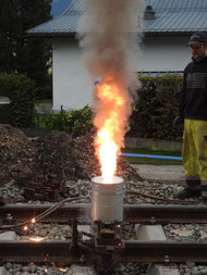
10:38:15 Begin of the exothermic reaction

The molten steel runs into the mould and melts the rail ends. The molten weld metal fills the gap and overflows into two collecting pots at the riser channels, which have to be removed at a later stage.[2]


The molten steel runs into the mould, fills it up and overflows along riser channels, melting the rail ends slightly.[2]
After about 3 minutes the steel has solidified in the mould. Afterwards, the retaining plates which compressed the split moulds can be carefully removed.[1]


After solidification, the casting half moulds are only removed above the upper edge of the rail.


The head bead above the top of the rail is carefully cut off with a hydraulic shearing device. The foot risers and the remaining parts of the moulds remain at the weld or at the rail, until the
weld has cooled down. When cleaning the weld joint of moulding sand residues and remnants of the split moulds, the hot rail must not be touched by using the hammer ot other impact
tools.[1]


After shearing off the flash at the rail head, the running surface and the running edge are pre-ground while still hot.[1]


Grinding is intended to achieve a rail surface and running edge that is as flat as possible, as it will come into contact with the running surfaces, wheel flange flanks and wheel flanges during
operation.


Finally, it must be assessed, whether the weld meets the quality requirements, before it is approved for railway operation.


Did you know...
- … that George Pellissier was the first American to use Thermit Welding commercially for laying 1 mile of track of the Holyoke Street Railway in Massachusetts?
See also
References
-
Matthias Müller, Thorsten Schaeffer:
Schweißverfahren mit
Kurzvorwärmung (SkV). Gleisbau Welt (Memento of 18. März 2004 in Internet Archive) 2003–2012, retrieved on 20. April 2019.
- Helium 4 et al: Thermitreation. German Wikipedia, Creative-Commons-Lizence Attribution-ShareAlike 3.0 Unported (CC-BY-SA-3.0).
Licence

The text of this article is available under the „Creative Commons Attribution-ShareAlike 3.0 Unported“ (CC BY-SA 3.0) licence.