
FSW: Tool Heel Plunge Depth

How to Set the Pin Length and Tool Heel Plunge Depth for Friction Stir Welding?
Choosing the correct pin length and setting the appropriate tool heel plunge depth are two of the key issues for obtaining high-quality friction stir welds with a fully welded root.
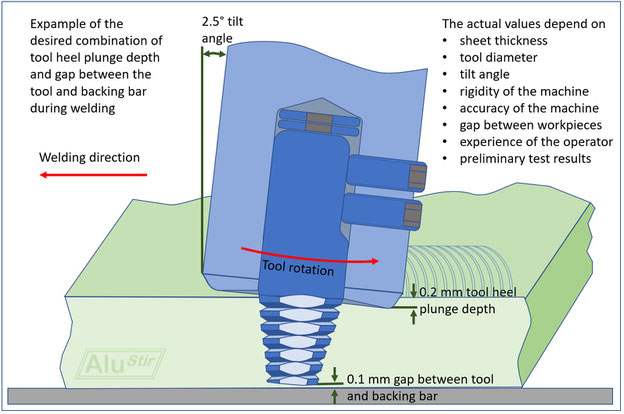
Expample of the desired combination of tool heel plunge depth and gap between the tool and backing bar during welding
© AluStir
The tool heel plunge depth and the gap between the tool and backing bar during welding are set correctly, if the plasticised material is sufficiently compressed during welding, while the pin does not touch the backing bar. The pin will be plastically deformed or the backing bar will be damaged, if the pin touches the backing bar. If the pin is too far away from the backing bar, the root will not be completely welded due to a lack of penetration. Colloquially this is often called “kissing bond”, because the two workpieces are just pressed against each other without disrupting the surface. This is difficult to detect by visual assessment or non-destructive testing, but becomes problematic during bend testing or during service.
The actual values depend on
- Sheet thickness
- Tool diameter
- Tilt angle
- Rigidity of the machine
- Accuracy of the machine
- Gap between the workpieces
- Experience of the operator
- Preliminary test results
If a conventional milling machine is used for FSW, or if a bespoke FSW machine is used in position control mode, the pin length needs to be adjusted according to the actual thickness of the thinner workpiece and the tool heel plunge depth has to be set, to ensure that the plasticised material is sufficiently forged into the joint line.
Setting the tool heel plunge depth is not required, if a CNC machine is used in force control mode, but the pin length needs still to be adjusted according to the actual thickness and/or the foreseen tolerances of the workpieces.
If the FSW tool is made from two pieces, and possibly even from different materials, the appropriate pin length can be adjusted using a set of washers or shims and one or two grab screws. The washers ensure that the pin does not move upwards during plunging or welding and the grab screws transfer the torque and ensure that is kept in the set position. If they are insufficiently tightened, the pin will slip in the shoulder. More sophisticated methods of inserting the pin in the shoulder are often used, e.g. a threaded connection between pin and shoulder, an adjustable securing bolt in the centre line of the tool, non-cylindrical cross sections e.g. for FSW of steel with brittle tool pin materials, and even adjustable pin tools, where the length of the pin can be changed before or during welding. At the end of a friction stir weld, the pin might be retracted into the shoulder to close the end hole.
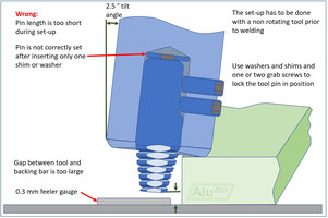
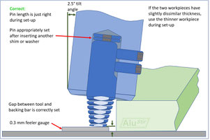
A pragmatic approach is, to use a feeler gauge during set-up, which has the same thickness as the sum of the desired THPD and the desired gap between the non-rotating tool and the desired gap between the tool and the backing bar. This gap should be chosen as small as possible, but if it is too small, either the pin or the backing bar will be damaged during welding. If the gap is too large, e.g. if kissing bonds occur although the surface of the weld looks good, then the tool needs to be disassembled, possibly chemically or mechanically cleaned and then re-assembled with the pin in a lower position by inserting another pin or washer.
A feeler gauge should be used to check the gap between the tool and the backing bar while pressing the heel of the tilted friction stir welding tool onto one of the workpieces. The same load should be applied, as normally used on such a machine. If one workpiece is thinner than the other workpiece, the thinner workpiece should be used for the initial set-up, to avoid touching the backing bar during the first trials. The setting should be confirmed or readjusted after the examining the first welds metallographically and by bend tests.
This hands-on method is very simple and can be use anywhere without the need for calibrated measuring tools. If digital read-outs or CNC machines are available it might be faster to use their measurement capabilities, keeping in mind that deflection mapping might be required if the machine deforms elastically due to the high forces applied during FSW.
Please contact stephan.kallee@alustir.com if you need help on adjusting your pin length and setting the tool heel plunge depth.