


Semi-automatic arc welding with up to 2 m long stick electrodes under a copper rail, invented in Austria in 1938
Firecracker Welding (German:
Elin Hafergut Process) was invented by Georg Hafergut around 1938 in Austria and was subsequently modified. In this process,
up to 2 m long flux-coated stick electrodes were melted automatically without mechanical equipment. The electrode was placed along its length on the seam forming the opposite pole, clamped
to the power source at its bare end and an arc was struck the opposite end, which then burned along the length of the electrode.
This arc welding process did not require any special manual skill on and was the only one working with a horizontal electrode at the time of its invention. However, it had originally so many
disadvantages that it did not gain much practical significance.
The electrode sometimes buckled upwards because it was bent by the ohmic resistance of its core, the arc burned inconsistantly and went out again and again, the penetration was only
slight.[1]
Improvements Using Grooved Copper Rails (1938)
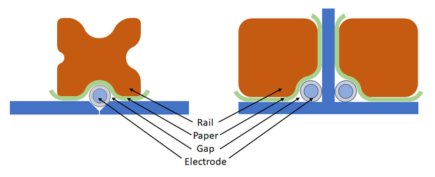
Firecracker welding: On the left the arrangement for V-joints and on the right for single or double-sided simultaneous welding of fillet welds. A
cavity is to be left between the workpiece, electrode and cover bar by forming suitable grooves in the latter, to absorb the slag produced during melting.[1]
© AluStir
Hafergut improved the process by placing a profiled copper bar, which was well clamped to the workpiece, over the flux-coated rod electrode shown in the illustration.[2]
Other metals were not suitable for the production of the cover rail. As shown in the illustration, the rail could be provided with grooves of different radii at all four corners in order to be
able to use it for different electrodes with 2 to 10 mm diameter.
A paper strip, e.g. made of packing paper, clamped between the electrode and the workpiece improved the welding result and operational safety. This arrangement not only improved fusion
penetration but also ensured a uniform flow of the melt and slag due to the closed channel. This kept the arc length constant so that seams could be produced with a uniformity otherwise only
achievable by automatic welding machines.
The left part of the figure illustrates the arrangement for V-seams, the right part the arrangement for single or double-sided simultaneous welding of fillet welds. A cavity should be left
between the workpiece, electrode and cover bar by suitable grooving in the latter, which can absorb the slag produced during melting.[1]

If possible, the beam should be turned during welding so that the flat position (PA).[3]
When working with direct current, polarity and current intensity are approximately the same as for manual electric welding. In practice, however, alternating current has proved to be the best
choice, because the unfavourable deflection of the arc due to the blowing effect is lowest here.
Since the electrodes cannot be loaded with higher current than in manual welding, this method was only economical if a welder could operate several welding points simultaneously using suitable
equipment. It was only of importance where bulk goods were welded whose seams were not accessible for manual electric welding.[1]
Benefits
- The process is semi-automatic
- No special manual skills of the operator required
- The required equipment is simple and cheap like that used for manual electric welding
- Faster than manual electric welding, as the electrodes do not need to be changed
- Porosity and slag inclusion of the finished weld is reduced because electrode positioning is consistent and accurate
- The procedure can be used in inaccessible places and in poor visibility[4]
Limitations
- Limited penetration
- The single-layer weld bead cannot have a larger cross section than the metal rod of the electrode, as it cannot be oscillated
-
Multi-layer welds were not common
- The process is limited to straight welds in horizontal position[4]
Industrial Applications (1950)
- Welding methods according to Ellira and Elin-Hafergut were used extensively for the Rhine bridge Düsseldorf-Neuss (today: Josef-Kardinal-Frings-Brücke) built in 1950-51. Before the actual assembly of the large bridge parts, the stiffeners of the side walls consisting of web with belt and the cross beams of the roadway slabs were welded according to Elin-Hafergut. The official designation of the steel was "Baustahl St 50 mit erhöhter Streckgrenze" or short "St 50 m. e. S.". The steel mill at Reinische Röhrenwerke AG called it "H.S.B. 50" (hochwertiger schweißunempfindlicher Baustahl - high-quality weldable structural steel).[5]
Scientific Studies in the USA (1975)
R.M. Evans and R.P. Meister of Batelle Columbus Laboratories carried out a comprehensive study in 1975 for the Bethlehem Steel corporation and under the support of the U. S. Maritime. Horizontal fillet and groove welds were made successfully, both with single or multi pass beads. The conclusions can be summarised as follows:[6]
- Standard electrode AWS E6027 produced a consistent bead in single pass 5/16 inch (8 mm) fillet welds with a length of up to 60 inches (1500 mm).
- AC welding current is preferred.
- Welding currents for firecracker welding are significantly lower than those of conventional stick welding. The voltage is consequently is higher (30-40V).
- Commercial glass-filament adhesive strapping tape can be used for welds up to at least 24 inches (600 mm) long. A non-commercial tape was suitable for welds up to 60 inches (1500 mm) long.
- Mechanical hold-down systems, grooved copper blocks and magnetic hold-down systems can also be used.
- Firecracker welds can be made over tack welds if the tack fillet size is less than 1/4 inch (6 mm).
- Multipass fillet welds can be produced by fire cracker welding using electrodes with different diameters should
- Arc instability and spatter are greatly increased when a primer is present.
For groove welds slightly higher welding currents, lower voltage and higher power inputs should be used than for fillet welds - The preferred groove for V-groove welds has a 60-degree included angle and a 1/4-inch (6,3 mm) root gap, which was backed with a flat steel bar.
- Problems when starting or stopping and reinitiating a firecracker fillet weld are similar to those of conventional stick welding, requiring a suitable preparation of the crater at the end of the weld bead.
- Satisfactory crater filling at the end of a weld is obtained by gradually reducing the welding current, but a cavity is produced at the root by this procedure.[6]
Recommendations (1975)
The conduction of further studies have been proposed in 1975 as follows:[6]
- Examine and improve the flux compositions
- Devise and evaluate a new hold-down tape
- Examine the value of shaping the core of electrodes
- Develop refined methods of stopping and restarting beads
Improve the end configuration of firecracker welds regarding their mechanical properties - Develop procedures for larger diameter electrodes, e.g. 1/4-inch (8 mm)
- Develop methods of increasing the size of tack welds[6]
- Develop procedures for vertical welds, to increase their size and minimise their concavity
- Assess the effect of using modern power sources
Patent (1938)
- Georg Hafergut, Weiz ('Elin' Aktiengesellschaft für elektrische Industrie, Vienna): Process and device for electric arc welding. US Patent No. US2269369A. Application 17 July 1939, Serial-No. 284,940, in Germany 2 December 1938.
References
- Paul Schimpke and Hans A. Horn (TÜV Berlin): Praktisches Handbuch der gesamten Schweißtechnik: Zweiter Band, Elektrische
Schweißtechnik. Springer Verlag, Berlin, Göttingen, Heidelberg, 1950, p. 152.
-
Schiffbautechnische Gesellschaft, Berlin: Jahrbuch der
Schiffbautechnischen
Gesellschaft: im Fachverband „Schiffahrtstechnik“ des NS-Bundes Deutscher Technik. Vol 43. Deutsche Verlagswerke Strauß, Vetter & Co, Berlin, 1942, p. 208.
- Dag Du Rietz, Helmut Koch: Praktisches Handbuch der Lichtbogenschweissung. Springer-Verlag, 1948.
-
Firecracker Welding on
Wikipedia.
-
Denkschrift zum Wiederaufbau der Rheinbrücke Düsseldorf-Neuss 1950–1951. Edited by
Stadt Düsseldorf, p. 47.
-
R.M. Evans and R.P. Meister (Batelle Columbus Laboratories for the
Bethleha Steel corporation and under the support of the U. S. Maritime
Administration): Applicability of firecracker welding to ship production. 31 July 1975. Retrieved on 14 June 2020.